Parameters and Attributes
Almost every value in every object, operator, generator, and parameter node can be Exported no that it has its own input. This is a powerful feature that allows you to control a node's properties from the modify panel to make sharing and reusing your styles a lot easier, or you can build numerical relationships between parts of the graph using exported attributes and arithmetic operations.
Exporting Parameters
Exporting Parameters is very simple. Right click on any node and at the bottom of the menu is an option to Export Parameters that contains a list of all the values that can be exposed to create a new input.
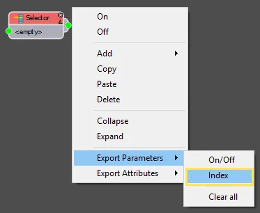
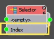
Just select the property and new input will be created at the bottom of the node.
Once you've exposed a property it can be wired to 4 types of other node:
1. Constant Nodes
Constant nodes allow you to enter a value that can only be changed from within the style editor. Unlike the Numeric node, this property cannot be animated.
2. Numeric Nodes
Numeric nodes are used to create values that can be edited outside the style editor in the Modify panel. They are commonly used to create a simplified interface so that the user can interact with the style without needing to open or understand the Style Editor. Unlike the Constant node, this value can be animated.
3. Exported Attributes
The current size of a segment's bounding box can be exported from virtually any node. The process is very similar to exporting a parameter, just right-click on a node, select Export Attribute and choose the parameter to be exported. The new exposed Attributes will be added to the bottom of the list of output slots.
4. Arithmetic Nodes
Arithmetic nodes are used to perform common mathematical operations on values from attached numeric nodes, constant nodes , and attributes. Using expressions it is also possible to access a number of advanced variables and functions.
Exercises
In this chapter, to illustrate how expressions work we'll make a tile pattern from a single box object. Using expressions we can include the following features, all of which will adjustable from the modify panel:
-
Create a pattern with alternating rows and columns of half sized tiles. The size of the small tiles are automatically calculated based on the dimensions of the large tile.
-
Ability to adjust the height width and length of the large tiles from the modify panel.
-
Ability to rotate the style from the modify panel.
-
Ability to toggle on/off or off the rows and columns of half size patterns.
Please see the video below for a preview of this style.
Exercise: Setting up the style
Before we start exporting and wiring parameters let's create the basic style. In the scene file for this chapter only a single box and an empty RailClone Style is supplied. Add the large tiles and create the initial array by following these steps.
-
Open
chapter_3_expressions_start.maxfrom the downloads for this guide. -
Select the RailClone object and open the Style Editor.
-
Create a new 2D array by dragging an A2S generator from the Items List to the Construction View.
-
Create a new Spline node and wire this to the Generator's Clipping Spline input.
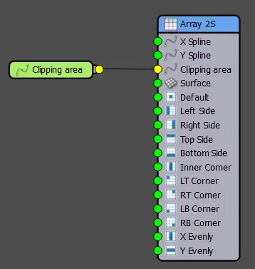
-
The clipping spline can be used to automatically set the size of the array, to do this select the generator and turn on Extend X/Y Size to area from the properties.
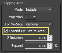
This feature is discussed in more detail in Chapter 6 of this guide.
-
Select the Spline node, click on
 from the Properties panel and pick
 boundary_splinefrom the scene. The array will be created so that it fills the area represented by this spline. -
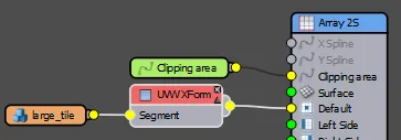
To add the tile geometry, create a new Segment node, go to the properties panel and click
then pick large_tilefrom the scene. -
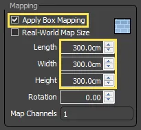
Because we're going to rescale this segment, and we don't want the textures to become distorted we can automatically box map the geometry directly in RailClone. To do this, select the segment node and go to the Deform tab of the Properties Panel. Turn on Apply Box Mapping and enter a value of 300cm for the Length Width and Height.
-
You will now have a simple tile style. Notice though that though we have mapped the geometry, the texture on each tile is identical. To add some variation we can randomise the uv mapping coordinates. To do this add a UVW XForm operator and wire it between the segment and the generator.
-
Select the UVW XForm operator and open the Random tab in the Properties Panel. Turn on Offset and enter a value of
-150cmforUandV \* Minand150cmin the U and V Max. Also turn on Rotation and enter a value of360for theMaxwith a step value of 90.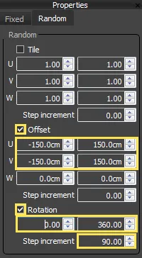
We'll look at the UVW Mapping and UVW Xform options in more detail in the next chapter
Exercise: Exporting Parameters and editing them from the Modify Panel
In this exercise we'll add some controls so the size of the tile and rotation of the entire array can be controlled from the modify panel. To achieve both these tasks it is necessary to export the parameters and attach them to a Numeric node. This is one of two types of node in which you can enter an integer, float, scene units, percentage or boolean value. The other type is called a Constant and differs only in that you cannot adjust it from the Modify panel. Generally speaking you would want to use Numeric Nodes where the value is likely to be changed regularly and Constant nodes when the value should remain unchanged.
-
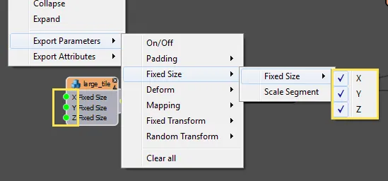
Select the Segment node and Right Click. The Export Parameters options are at the bottom of the Right-Click Menu. Choose Fixed Size > Fixed Size > X and a new input appears on the Segment node. Do the same thing to export the Y and Z fixed size parameters.
-
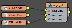
Create 3 new Numeric nodes, one for each exported parameter and wire them to the size inputs. You'll notice that the names of the Numeric nodes change automatically to reflect the input's they're wired to but if you want to name them manually you can do so from the Properties Panel.
-
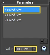
For each Numeric node, go to the Properties Panel and change the type to Scene Units. You can also set the numeric type to float, integer, percentage or boolean but for dimensions scene units is the logical choice.
-
RailClone's Modify Panel interface has a rollout called Parameters. This contains editable values for any Numeric nodes found in the style. In the Parameters List you should see the 3 Size values we created in the previous step. If you edit these values, the geometry in the style is resized!
 caution
If you enter a very small value in the X or Y fixed size you may get a warning about exceeding the segment counts.
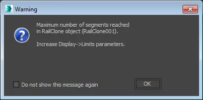
This happens because the small geometry size has caused too many segments to be created. If you increase the size the object should display correctly.
If you wish to avoid this issue you can set a minimum and maximum limit for the value by selecting the Numeric node in the Style Editor and turning on Limits.
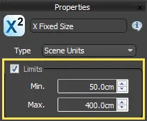
However in this example I chose not to do this because when the Fixed Size parameter uses a value of 0, the dimensions of the original geometry are used instead. This gives me the option to set a size manually by entering a value, or use the original dimensions by leaving them set to 0.
-
It is also possible to export parameters from Generators. In this example we'll export the Z rotation property, so it can be adjusted from the Modify Panel. Right-click on the Generator and go to Export Parameters > Clipping > Z Rotation.
-
Create a new Numeric node and wire it to the Z Rotation input.
-
From the Properties Panel, change the Numeric node's Type to Float. Float makes sense in this case as the rotation value is measured in degrees.
-
In the Modify Panel, you will now have a new Z Rotation parameter. Changing this value rotates the entire array within the clipping spline.
Exercise: Exporting Attributes and simple maths with the Arithmetic operator
Now that we have the main tile finished we can add the alternating rows of half sized tiles.
-
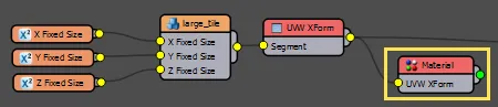
Firstly, change the material for the smaller tile. To do this, add a new Material operator and wire the output from the UVW XForm operator to the Material node's input.
-
Select the Material node and from the properties panel, change the From and To value to 2 There is already a multi-sub object material applied that has a grey texture in ID slot 2.
-
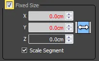
Add a new Transform operator and wire the Material Node to its input. Transform operators allow you to re-use geometry by changing the padding, alignment, fixed size and transforms without affecting the original. In this example we will use the transform operator to scale the tile to half the size, so open the Properties and turn on the Fixed Size override toggle button.
-
To be able to control the Fixed Size we'll export the X and Y size parameters. Right-click on the Transform node and click Export Parameters > Fixed Size > Fixed Size > X and Y.
-
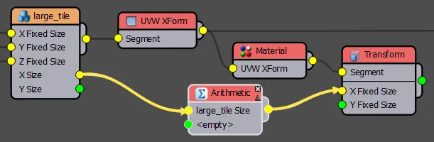
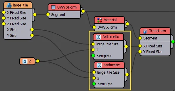
Next we need to get the existing size of the large tile. To do this you can export Attributes from any node. These will give you the current X Y and Z dimensions from any node at any point in the graph. Right-click on the Segment node and select Export Attributes > Size > X and Y.
-
To calculate the new size of the small tiles, create a new Arithmetic node and wire the Segment's X size output to the Arithmetic node's first input.
-
Wire the Arithmetic node's output to the Transform nodes X Fixed Size input.
-
To divide the value in half, add a Constant node and enter a value of 2 in the Properties panel. Wire this to the Arithmetic node's second input.
-
Select the Arithmetic node. If you go to the properties panel you'll see it has many different operations including add, subtract, divide, maximum and minimum. In this case set the operation to Divide.
-
To calculate the Y size of the small tile we just need to repeat this process. create a new Arithmetic node and wire the Segment's Y size output to the second Arithmetic node's first input. Wire the Arithmetic node's output to the Transform nodes Y Fixed Size Input. Wire the existing constant to its second input and set the mode to Divide. This will now generate a half sized segment on both axes.
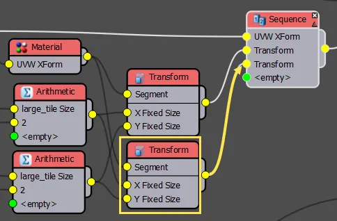
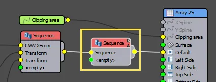
- To see this in the style, wire a Sequence operator to the Generator's Default input. Wire the UVW Xform node to the first input, and wire the Transform operator to the second input.
Congratulations! you have now exported values to control the size of tiles from the modify panel and used attributes and arithmetic nodes to automatically generate tiles that are always half the size of the main tile. In the next exercise we'll move the tiles into the correct position using padding and fixed transform nodes with a simple expression.
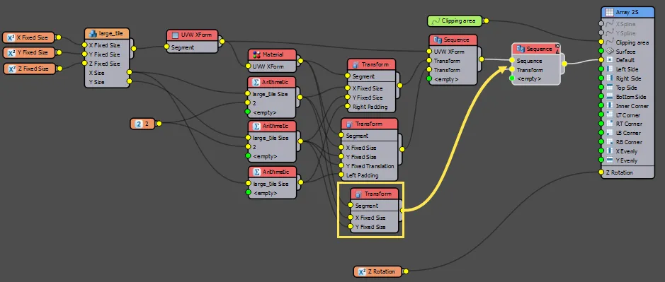
Exercise: Using Expressions
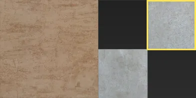
If you have completed the previous exercise correctly, there should be a repeating pattern on the X axis of a large tile followed by a half size tile. Next we need to add a second small tile in the gap marked in yellow in the diagram below:
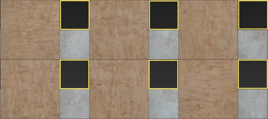
To do this we will need to add another small tile to the sequence, and then move it left and up into the correct position.
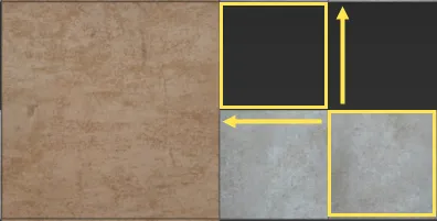
Moving the tile up is easy enough, we can use the Y Fixed Translatedroperty and the existing Arithmetic node that's being used to calculate the tile's Y Size. However, to move it to the left we can't use X Fixed Translate because it will leave a gap in the array.
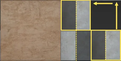
Instead, we need to use Padding. Here thought there is a slight problem, in order to align correctly, the padding value needs to be the same as the width of the tile which will result in a segment that has no measurement on the X axis (tile width - tile width = 0). A segment with a size of 0 is disregarded in RailClone, as it can potentially result in the creation of an infinite number of segments. To get around this we deduct half of the size of the small tile from the right of the first segment, and half from the left of the second small segment. In the image below the padding on the tiles is marked in dark grey, as you can see when you disregard these areas the second tile slides to the left and into the correct position.
-
To create the padding we will need to duplicate the existing Transform node as the two small tiles need to have different settings. To do this, select the Transform node, right click and then select Copy. Right click again and select Paste.
-
Wire the new Transform operator to the Sequence operator's third input.
-
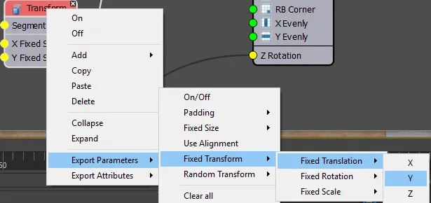
To move the new segment up, Right click on its Transform node and select Export Parameters > Fixed Transform > Fixed Translation > Y.
-
Wire the existing Arithmetic node that is used to calculate the height of the small tile to the Y Fixed Translation Input the tile will now move up the height of one tile.
-
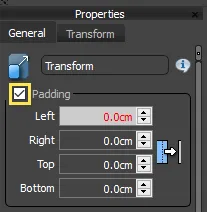
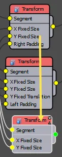
To add the Padding, export the Padding > Right Padding value for the first small tile and Padding > Left Padding for the second small tile
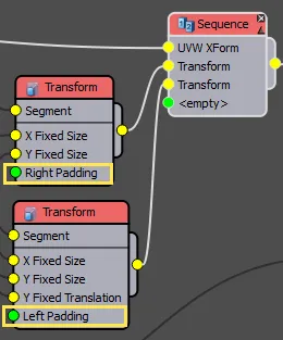
-
Turn on Padding in both Transform nodes. Note that exported values are shown in red
-
The padding value for both of these inputs needs to be half the width of the small tile. Because the small tile is already half the width of the large tile, this means the padding value is a quarter of the width of the large tile. Additionally, to cause the tiles to overlap, it should be a negative value. We could do this by wiring together two arithmetic nodes like this:
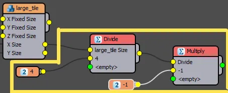
If we were to express this in standard mathematical notation then this set of 4 nodes is creating the equation
-1 * (X Size / 4).However, we had to use quite a few nodes to create that simple equation, so another option is to use the Arithmetic Operator's Expression Editor to enter the equation using standard mathematical notation. To do this add a new Arithmetic node to the graph and wire its output to the two Padding values you just exported.
-
Wire the
Large_tilesegment's X Size attribute to the input of the new Arithmetic node. -
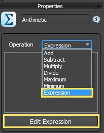
Select the Arithmetic node and change the mode to Expression from the Properties Panel
-
Click on Edit Expression to open the Expressions Editor window.
Expressions-
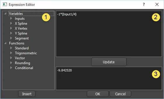
The expressions editor window
The expressions editor window is spline into 3 parts:
-
Expressions pane. Found on the left, lists all usable variables and functions. Double click a list item to add it to the edit window or single click to display help.
-
Edit Window. Used to create and edit the expression, to see the effects of an expression press Update. To construct a variable you can either type it in manually or add variables and functions by double clicking them from the expressions list.
-
Expressions Help. This window provides information about the currently selected variable or function or displays the output of the expression.
The editor uses the same syntax as you will find in the expression controllers found elsewhere in Max.
This consists of a a straightforward mathematical syntax comprising operators
+, -, *, /, etc, constants (pi, e, etc.), RailClone's built-in variables, numerical inputs, and functions ( including standard, trigonometric, vector, rounding, and conditional functions that take one or more arguments and return a result).To find out which built in functions, operators and constants are available, a full list is included in the Expressions Pane in the left hand side of the window.
To see an explanation for each function, single click on it and a description and example syntax will display in the Expressions Help panel at the bottom of the interface.
You can read more about this and see a full list of supported arithmetic operations in Autodesk's documentation here (with the exception of the predefined variables with variable values, which are not supported). In addition to the functions supplied by Max's expression class, we have added a number of RailClone specific variables. You see in the list on the right of the Expression editor and clicking on each of these will give you a brief description, but for convenience a summary is below.
-
-
Inputs
Input1,2,3, ... nthese refer to any value wired into the Arithmetic nodes inputs. The number relates to the input slot counting from the top down.-
Spline Variables
XSplineCoords,YSplineCoordsrefers to the position of the current segment over the Spline on the local coordinates measured from the RailClone objects pivot point. To access the value for a particular axis, the X axis for example, you must append a .x,.y,or .z to the end of the variable, e.g. XSplineCoords.x`XSectionLength, YSectionLength returns the length in scene units of the current section where a section is the path between two Start, End, Corner or Evenly segments.
XSplineLength, YSplineLengthreturns the length in scene units of the current spline.XSplinePosition, YSplinePositionreturns the position of the current segment on the spline. This is measured not as an absolute measurement in scene units but a decimal value between 0 and 1 that represents the position of the current segment along the spline.XSectionPosition, YSectionPositionis above but instead of returning the position along the spline, returns the position along the spline section where a section is the path between two Start, End, Corner or Evenly segments.XSplineTypereturns 0 if the spline is a line and 1 if it is a curve. Useful for conditional statements.XSplineMatIDreturns the material ID applied to the current spline section.-
X Vertex
XVertexTypereturns 0 if the current or previous vertex is of the type smooth, 1 if it is a corner, 2 if a Bezier, and 3 if it is a Bezier-Corner. Useful for conditional statements.XVertexAnglereturns the Angle between X Spline segments on the current vertex measured between0andPIradians. (0 - 180 degrees when converted)XVertexWideAnglereturns the angle between X Spline segments on current vertex measured between0and2 * PIradians. (0 - 360 degrees when converted)-
Segments
SegmentXCounter, SegmentYCounterreturns the current segment's index along the path. Note that there are two separate counters: one for default segments, and another for Start/End/Corner/Evenly combined. -
-
Enter the expression
-1 * (Input1/4). In these expressions Input1 is the value piped in by the node connected to the first input. 12. The style will now be updated with an alternating pattern of one large tile, followed by two small tiles one above the other. If you edit the size of the large tile, the small tiles also adjust automatically.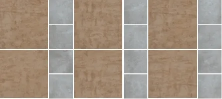
Exercise: Creating the horizontal rows of small tiles
The style is nearly complete, we just need to create the alternating horizontal rows of small tiles. To do this, follow these steps.
-
Create a new Sequence operator and wire it between the existing Sequence operator and the Generator's Default Input
-
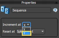
Select the new Sequence operator and change the mode to Increment in Y from the Properties Panel.
-
We don't need the segments in these rows to overlap, so Copy and past the first of the existing Transform nodes and then right click and turn Off the exported Padding parameter.
-
Wire the third (new) Transform operator to the new Sequence operator's second input.
-
You now have a style with alternating rows and columns of small and large tiles with adjustable size on the X, Y, and Z axis and Rotation!
Exercise: Turning on/off features
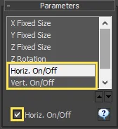
Finally, we'll add one last function to the style and demonstrate how to disable nodes so that features of a style can be turned on and off from the modify panel. In this example we'll provide two tick boxes that turn on or off the horizontal or vertical rows of small tiles by enabling and disabling the two sequence operators.
When a node with multiple inputs is disabled, the geometry wired to the first input is passed on to the next active node in the graph. Any geometry in the other inputs is ignored. In this example we are using Sequence operators so disabling them will allow the first input to continue to the generator, disabling the pattern caused by the node.
-
Right click on both Sequence generators and Export the On/Off parameters.
-
For each of these exported parameters create a new Numeric node and set the Type to Boolean.
-
Give each one an appropriate name and wire it to the exported On/Off inputs. You can now turn these nodes off by clicking the check-boxes found in the Parameters rollout of the Modify Panel.
This completes the tiling style. If you've followed all the exercises in this chapter you will have exported parameters and attributes, created numeric nodes to control aspects of the style from the modify panel and used constant nodes to set fixed values. You will also have used the expression editor to create a simple equation and minimise the number of nodes that need to be created for common mathematical functions. In the next chapter we'll look at material IDs and UVws and use exported values to take more advanced control material ID randomisation.
Related Tutorials
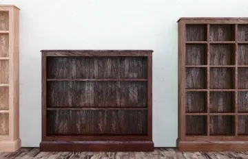
In this Tips & Tricks tutorial we look at how RailClone can be used to create procedural furniture. Follow this exercise to learn how to export many properties to allow a user to adjust the height, width and shelf distance of a bookshelf directly from the modify panel
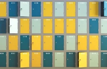
For some styles it is necessary to create numbers that increment for each segment. In this Tips and Tricks episode we look at two ways to create sequences of numbers. The first example illustrates how to create a series of numbers by cycling through geometry. In the second part we manipulate a segment's material IDs using expressions to create numbers using multi-sub object materials.
In this advanced exercise we look at a
time saving graph-snippet for mapping segments and randomizing them with individual tiles or bricks from textures.
This tutorial features numeric, constant, arithmetic nodes and exported attributes.

In the second part of this intermediate tutorial on creating bridges we demonstrate how to use the arithmetic node and expressions to create a bridge with a deck that is able to deform on the Z axis with piers that automatically scale to support it.
For more information please see the Segments, 2D arrays - Generator A2S, 1D arrays - Generator L1S, Exporting Parameters and Arithmetic sections of the online documentation.