2D arrays - Generator A2S
Overview
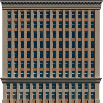
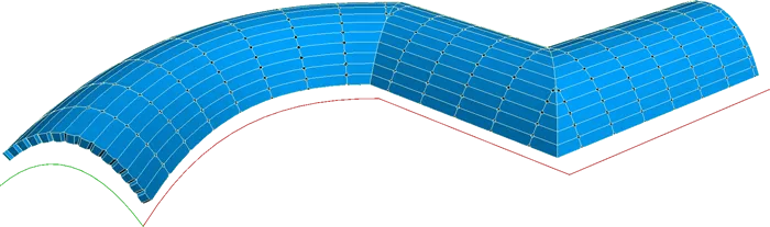
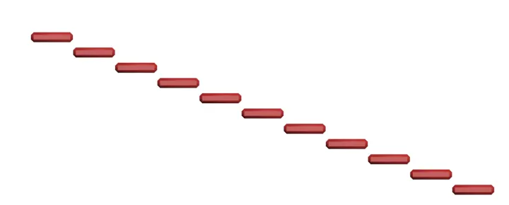
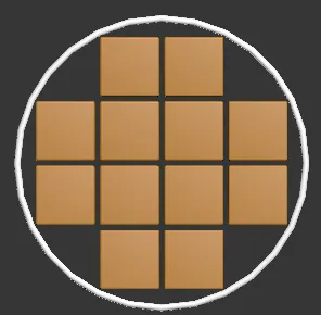
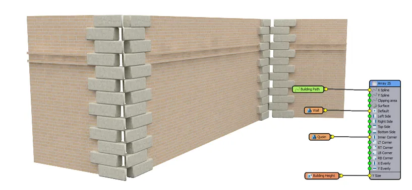
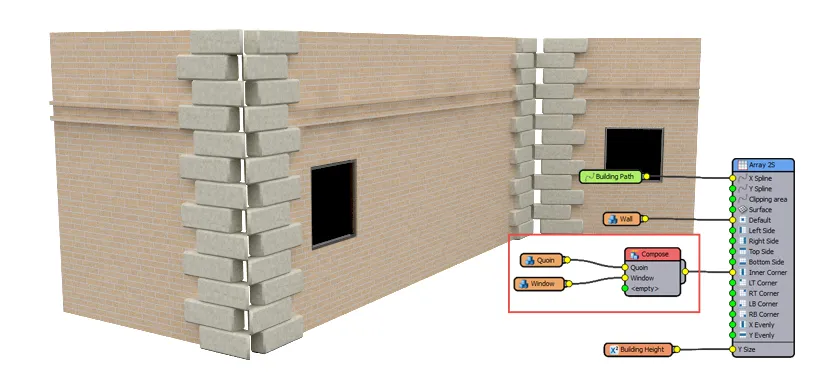
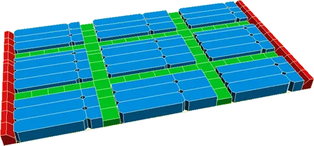
A facade created using the A2S Generator
The A2S generator is one of two types of Generator included with RailClone. A2S creates a 2D array based on dimensions provided numerically, or by using splines as paths. When the latter is used complex double curved geometry is possible.
Generators use a set of construction rules that determine how segments are combined to build parametric objects. The interplay of generators, segments, base objects and rules is called a style. Because RailClone is fully procedural, simply changing the base objects or parameters will update every component referenced in the current style. The video below demonstrates a simple facade that uses an A2S generator controlled by two splines.
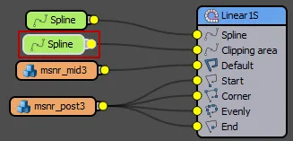
The A2S generator has a number of possible input segments. These are listed below with a short explanation. Click on a name to read the full reference.
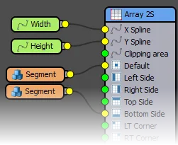
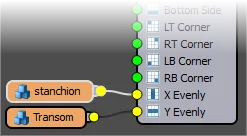
- X Spline: Uses a Spline input to identify the object in the scene used to determine the X axis of the array.
- Y Spline: Uses a Spline input to identify the object in the scene used to determine the Y axis of the array.
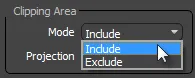
- Clipping Area: Uses a single closed spline to cut through the RailClone object. Clipping splines can be set to include or exclude geometry.
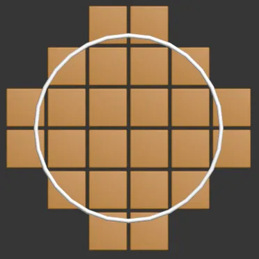
It is possible to generate an A2S style without splines using the X and Y size properties of the generator. However, at least one of the following inputs must be used in order for the A2S generator to create geometry. The diagram below demonstrates how these segments are used to construct the facade in the example at the top of this page.
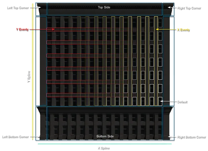
This diagram explains the different node slots used to create the facade above.
- Default: Used as the base mesh in the event that the other nodes have no inputs. If one of the following inputs is left empty, the segment wired to the default input will be used.
- Left Side: Creates segments along the Y axis on the left side of the 2D array.
- Right Side: Creates segments along the X axis on the right side of the 2D array
- Top Side: Creates segments along the X axis at the top of the 2D array
- Bottom Side: Creates segments along the X axis at the top of the 2D array
- Inner Corner: Creates a column of segments at each of the intermediary vertices of the construction spline. Can be set to only create a segment on certain types of vertex i.e. corner. bezier-corner, bezier, smooth, or on all of these.
- Left Top, Right Top, Left Bottom and Right Bottom Corners: Allows you to position a segment in each of the four corners of a 2d array.
- X Evenly: Creates evenly spaced columns.
- Y Evenly: Creates evenly spaced rows.
Procedures
To create a new A2S Generator
-
Create a new RailClone object by going to Create>Geometry>Itoo Software>RailClone Pro and dragging out a RailClone object in the viewport.
-
With the new RailClone object selected, go to the Style rollout and click on the Open Style Editor button
 .
. -
Drag a new A2S Generator (
 ) into the construction view
 -
Though it is possible to use the A2S generator without base objects, in this example we will use two splines to define the X and Y path of the 2D array
-
Drag two Spline objects into the construction view and wire them to the X Spline and Y Spline input slots of the A2S node.
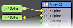
-
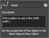
Rename each spline node so that its purpose is clear in the Base Objects rollout, if necessary add a description that will be used as a custom tooltip.
-
In 3DS Max Create two new editable splines, one to define the path for the width of the array, and another for the height.
-
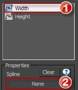
Go to the Base Objects rollout of the RailClone object. Click on each item in the list and select one of the splines you just created.
Once you've defined the array dimensions it's time to add some segments as described in the following procedures.
To add sides, corners, and default segments
It is possible to add separate segments for the top, bottom, left and right sides as well as each of the corners. As few or many of these inputs can be used, there is no requirement for every input slot to be occupied. In the event that a slot is empty the default segment will be used if one has been connected.
-
With the RailClone object selected, open the Style Editor (
) from the Styles rollout. -
From the Items List Drag a new Segment object (
 ) for each input you wish to use to the construction view. In this example we'll use the Default and Bottom slots, so we'll need two nodes.
 -
Connect each segment node to a corresponding input as in the image below.
-
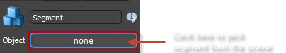
For each segment, go to the properties editor, click on the object selector and pick your geometry from the scene.
-
Adjust padding, alignment, deformation and transforms as required. See the Segments reference for more information.
To prevent clipping of segments at the start or end of the path
It is possible to automatically scale segments so that they fill a path with only whole segments, avoiding clipping at the start or end. Assuming you already have a segment in the default input:
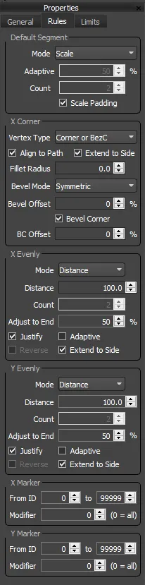
- From the Generator's properties, go to Rules>Default and set the mode to Adaptive.
- Set the Adaptive Percentage to control the minimum length of remaining space before a new segment is added (see the section below for a more detailed explanation).
To distribute evenly spaced segments on the X/Y axis based on distance
-
With a RailClone object selected, open the Style Editor (
) from the Style rollout. -
Create a new A2S Generator (
) as described above. -
Drag a new Segment object to the construction view for each unique geometry item you wish to use.
-
Wire the new segments to either of the X Evenly or Y Evenly nodes.
-
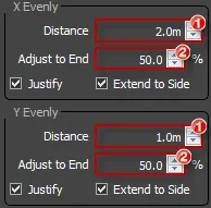
Select the A2S generator node and go to Properties>Rules>X Evenly/Y Evenly. Set the Mode to Distance and use the Distance parameter to adjust the spacing between the rows or columns. (marked 1 in the following image)
-
Enter the Adjust to End parameter (marked 2 in the image). This value determines the threshold at which a new row or column is added in the start and end spaces based on a percentage of the Distance, entered the previous step. For example, if the Distance is 10 metres and the Adjust to End percentage is 50%, a new row of segments will be added only when the final space is greater than 5 metres.
-
If you would like to equalise the first and last space of the evenly distributed segments, turn on Justify.
-
Turn on Adaptive node if you wish to equalise the spacing between all the evenly segments.
-
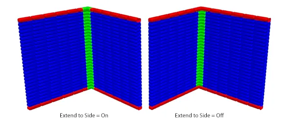
If you would like the evenly spaced segments to continue to the edges of the array interrupting the sides, top or bottom, turn on the Extend To Side option.
To distribute evenly spaced segments on the X/Y axis based on a fixed number of divisions
-
With a RailClone object selected, open the Style Editor (
) from the Style rollout. -
Create a new A2S Generator (
) as described above. -
Drag a new Segment object to the construction view for each unique geometry item you wish to use.
-
Wire the new segments to either of the X Evenly or Y Evenly nodes.
-
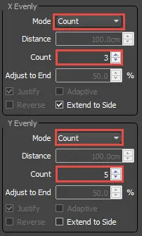
Select the A2S generator node and go to Properties>Rules>X Evenly/Y Evenly. Set the Mode to Count and set the Count parameter to determine the number of evenly spaced divisions to place along the spline.
-
If you would like the evenly spaced segments to continue to the edges of the array, interrupting the sides, top or bottom, turn on the Extend To Side option.
To create an A2S array without the need for splines
-
Create a new RailClone object and open the Style Editor (
). -
Drag a new A2S Generator (
) from the items list to the construction view. -
Do not create spline nodes, there is no need if you are creating a simple flat 2D Array.
-
Drag a new segment node from the Items List to the Construction View for each input you wish to use as described above.
-
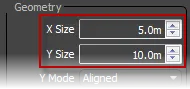
To create the array, select the A2S generator node and go to Properties>General>Geometry>X Size to set the width.
-
Next Go to Properties>Geometry>Y Size to set the height.
-
The array will be created on the XY plane of the world axis. Since it is not bound to any spline, if you need to rotate it simply use the Select and Rotate tool in the usual fashion.
Use a spline as a clipping area
-
From the Style rollout open the Style Editor
. -
Add a new Spline node
 .
. -
Wire the new Spline node to the Clipping input node of a generator
-
With the A2S Generator selected go to the Properties Editor and set the Clipping Mode to Include or Exclude is desired.
-
Close the Style editor. Go to the Base Objects rollout in the 3DS Max plugin, select the clipping item from the list and choose the spline from the scene.
To use a closed spline to define the size of an Array
- From the Style rollout open the Style Editor .
- Add a new Spline node .
- Wire the new Spline node to the Clipping input node of an A2S generator
- With the A2S Generator selected, go to the Properties Editor and enable Extend X/Y Size to Area.
- Change the Auto-Align node: X --> XY to ensure the array is parallel to the RailClone XY plane, To Spline will force the X axis to be aligned with the Spline's first segment.
To Cap Clipped Geometry
- Enable Cap Holes from the Generator's properties.
Interface
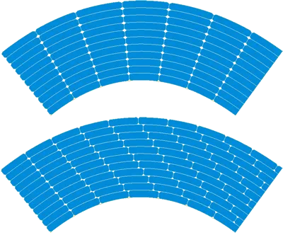
X/Y Spline
Defines the X and Y dimension and shape of the array. It is possible use the A2S generator without splines at all, in that case RailClone builds the array along the local X/Y axes, and the dimensions are defined by the X/Y Size parameters.
It is not necessary to align the Y spline in 3D space. Just create it on any XY plane, RailClone gets the origin and extent of the spline automatically, using the local X/Y vertex positions. Z is ignored.
Vault parametric structure defined by X/Y splines
Geometry
X/Y Size
Defines the size of the array when there are no X/Y Splines assigned (see above).
Y Spline
defines what coordinates are used for the Y Spline: Y/Z or X/Y.
Note that X/Y was the mode for RailClone 2 objects. RailClone 3 objects uses Y/Z mode by default, which is more logical.
Y Mode
The A2S generator can work in two different modes: Aligned and Free.
In Aligned mode, all segments along the Y path are scaled to maintain the same alignment as on X. Alternatively, free mode creates independent rows on Y, so each segment keeps its original size.
Each mode uses a different algorithm, so this parameter may generate very different results for the same Generator. When using Free mode you cannot use a Y Spline, the extent in this direction must be explicitly defined by the Y Size parameter.
X Offset
Applies the specified offset to the entire generator along the X path.
Y Offset
Moves the RailClone object the specified value
perpendicularly
to the path's direction.
Simple Y Offset
Standard Y-Offset uses a sophisticated algorithm to compute Y-Offset paths, but in some cases does not generate the expected result. Simple Y-Offset provides an alternative algorithm that may resolve these problems. Enable this mode if you get distorted geometry when using standard Y-Offset.
Z Offset
Displaces the geometry the specified value on the Z axis.
X Rotation
Rotates the segments along the direction of the X spline. This parameter has the same effect that Style ->Geometry->Rotation, but can be controlled interdependently for each to the generator. This is particularly useful if you are using multiple generators in a single style. When using local and global rotations, both values are added to get the total X rotation.
Slope
Rotates the array around the X Spline but does not affect the segments themselves, creating a stepped appearance. Angles are limited between 0 and 70 degrees.
Cap Holes
When checked, holes caused by boolean clipping and slicing are automatically capped. Faces generated from clipping areas are mapped using parameters from the Segment's Deform>Apply Box Mapping settings. Mapping parameters are taken directly from the Segment node, and are not affected by UVW XForm operators.
Material ID
Selects the material ID assigned to capped faces
Clipping Area
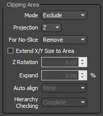
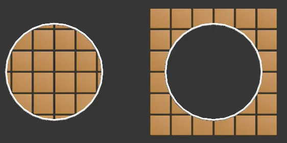
Uses a closed spline as a boundary region, using it to clip the geometry of the object. RailClone clipping is much more efficient that a 3DS Max boolean operation, and optimizes the instanced geometry when using the VRay/Mental Ray geometric shader.
Mode
Defines the clipping mode: Include preserves the geometry inside the area, and Exclude removes the geometry inside the area.
Projection
Clipping works in 2D, projecting the spline along the axis defined by this parameter (X,Y or Z in the local coordinates of the RailClone object).
Clipping area
For No Slice
Determine how to cull segments with their Slice parameter disabled. Choose from:
-
Remove. segments that intersect with the clipping spline are removed. No segments will extend beyond the clipping spline in this mode
-
Preserve. segments
that intersect with the clipping spline will be retained without slicing. Segments can extend beyond the clipping spline in this mode.
-
Slice. segments that intersect with the clipping spline are sliced. Segments will match the clipping spline exactly.
Extend X/Y Size to Area
Automatically create a size for the A2S array that is sufficient to fill the area defined by the clipping spline. In this mode there is no need to add X or Y Splines or values to define the size of the array.
Z Rotation
When Extend X/Y Size to area mode is enabled, this setting allows you to rotate the entire area inside the clipping area.
Expand
When Extend X/Y Size to area mode is enabled, this allows you to enlarge the size of the array. This can be useful for removing gaps around the perimeter in some styles.
Auto Align
This option creates array aligned automatically to each sub-spline when using Extend X/Y mode. It is ideal for roof and panels.
Two modes are available, for both modes Z axis is always perpendicular to the plane formed by the spline.
-
X --> XY In this mode the X axis is parallel to the RailClone XY plane (considering the local axis of the object).
-
To Spline In this mode the X axis is aligned with the Spline's first segment (you can use Make first vertex and Reversespline to modify alignment).
Hierarchy Checking
This options determines the way that RailClone processes multiple or stacked splines when using Extend X/Y Size mode.
-
Complete uses the original RC2 behaviour, stacked splines are alternatively include/exclude geometry
-
None treats each spline as unique, overlapping or stacking splines has no effect.
-
By Material ID uses the material ID assigned to the splines to determine which should be considered to belong to the same array.
UVW Offset
Allows you to offset the UVWs for all if the segments attached to the generator
Default
If there are no other applicable rules, RailClone uses this segment by default. There are two operation modes: Tile and Scale.
Tile
The segment is replicated along the X and Y path. RailClone applies the deformation parameters defined in the Segment properties, such as slicing the segment automatically to fit the path's length or applying the padding distances.
Scale
In this mode, the default segments are scaled along the X axis to fit the distance between the initial and final positions of the path section. A section is defined by the start and end points of the spline unless an X-Evenly or corner segment is used to subdivide the path. When scale mode is active the bevel settings are greyed out.
Adaptive
Adaptive mode calculates the number of whole segments that would fit along a spline segment then scales them on the X axis to fill the available space. This mode generates complete segments, with no clipping at the start or end of a spline segment.
Adaptive Percentage: this value specifies the minimum length of remaining space (expressed as a percentage of the segment's original size on the X axis), at which a new segment can be added. For example if a segment's X-dimension is 1m and the spline length is 4.25m, the segment will fit into the distance 4 times (4 x 1m = 4m). The remaining space is 0.25m, therefore a new segment will be added if the Adaptive Percentage is set at or below 25%.
Count Mode: scales a fixed number of segments to fit between the start and end positions of a path section. A section is defined by the start and end points of the spline unless an X-Evenly or corner segment is used to divide the path.
Count Parameter: defines the number of segments to scale along the path when Count Mode is enabled.
Scale Padding: then enabled any segment padding is scaled on Scale, Count, or Adaptive modes. If it is disabled, the padding is constant.
At present Adaptive mode only functions on the X axis, the Y axis will be clipped as though the mode is set to Tile
X Corners
Defines the segments to be used on the intermediary vertices of the base spline.
X Corner
This construction rule is used to create a column of segments on specified vertices of the X path.
Vertex Type
Describes the type of vertices that will use this rule from the following values: "Corner or Bezier-Corner", "Corner", "Bezier-Corner", "Bezier", "Smooth" or All.
Align to Path
Enable this option to create smooth transitions of the corner segment along the path's trajectory. When off, RailClone aligns the corner with the last segment of the spline.
Extend to Side
When on the corner segments will extend to the full height of the array, cutting through any segments that are in the Top and Bottom inputs. When off the Top and Bottom rows are continuous.
Fillet Radius
Adjusts the path to create a rounded corner. The numeric parameter defines the radius of the fillet arc.
Bevel Mode
There are four Bevel modes available, which determine the displacement of the Default segments before and after a bevel's edge.
- Reset. Each segment is placed at its default position (defined by the Alignment and Padding values), without applying any displacement.
- Extend: extends the geometry of the segments along the bevel, giving an appearance of continuity.
- Symmetric. Creates symmetrical geometries at both sides of the bevel's edge.
Symmetric Bevel
Offset
Applies a global displacement to all segments along the X path. The value is defined as a percentage of the segment's size (from 0% to 100%).
-
The Bevel feature works better on straight lines and wide corner angles. You would get incorrect results on narrow angles or curved paths.
-
When using closed splines, it's not possible to adjust the segment displacement for the last corner, because it is dependent on the path's length.
-
Bevel is not compatible with the Default segment in Scale mode.
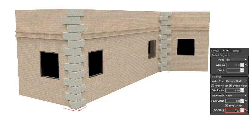
Bevel Corner
When active, bevels the segment attached to the corner input, slicing the geometry. If Bevel Corner is disabled, RailClone bends the geometry of the Corner segment around the corner.
The alignment of the geometry in relation to the Corner depends on the number of segments used in the Inner Corner input. The examples below explain how using a single, odd or even number of segments affects the alignment.
Segments used in this example
In the following examples these segments are used in the corner input. Where multiple segments are used, they are wired to a compose operator.
Using a single corner segment
When using a single segment in the corner input, the geometry is duplicated and a segment is placed on either side of the vertex. The position is adjusted to ensure that the full length, measured on the outside face and along the X axis, is maintained irrespective of the angle of the corner.
Using an even number of corner segments
Duplicates the segment immediately before the center then places other segments on left/right depending on order in the compose operator. Using an even number of segments always creates an asymmetric composition.
Using an uneven number of corner segments
Duplicates the center segment then places other segments on left/right depending on their order in the compose operator. Using an odd number of segments always creates a symmetrical composition.
Bevel Corner Offset
Allows you to adjust the offset of the Corner segments. Distance is measured as a percentage of the length of the corner segment. positive values pull the segment towards the corner, negative values will move the segments away from the corner. If a negative value is sufficiently large a gap will appear. The example below illustrates the effect of increasing the Offset value, bringing together and slicing the corner segments.
-
The Bevel feature works better on straight lines and wide corner angles. You will get incorrect results on narrow angles or curved paths.
-
In closed splines, it's not possible to adjust the segment displacement in the last corner, because it depends on the path's length.
-
Bevel is not compatible with the Default segment in Scale mode.
Evenly
X/Y Evenly
This construction rule lets you add evenly spaced segments along the X and Y paths.
Distance
Defines the distance between the evenly segments, specified in scene units by the Distance parameter.
Count
Defines a set number of evenly segments, specified by the value of the Count parameter.
Adjust to End
This value specifies the minimum length (as a percentage of the Distance parameter), at which a new evenly spaced segment can be added.
For instance: using a value of 40% and a Distance of 2m, RailClone only adds new segments if the length from the last even segment to the end of the spline is greater than 0.8m.
Justify
Centers the evenly spaced segments on the path, making the first and last spaces equal.
Adaptive To
Adaptive mode is used to ensure the spacing between Evenly segments is identical. This mode calculates the number of times the full Evenly distance can be distributed along the path then divides that number by the path's length to generate a new equalised spacing. 3 modes are available, either an off number of divisions, an even number, or any number,
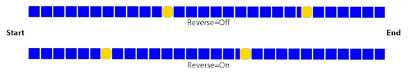
Reverse
If Justify or Adaptive mode are both off, the space between evenly segments will be measured at precise intervals from the start of the array. Use the reverse option to start the evenly measurements from the end of the array.
Extend to Side
When enabled, extends the evenly segments to the sides of the array cutting through any segments being used in the Sides, Top or Bottom inputs.
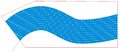
Array using Left/Right sides and X/Y Evenlies (green piece). Extend parameter is X:off, Y:on
Left/Right/Top/ Bottom Sides
Defines the segment for each one of the sides of the array structure. This rule has no adjustable parameters, just connect the side segment to the input in the generator's node.
LT/RT/LB/RB Corners
Defines the segments to be used at the corners of the 2D array. The abbreviations stand for Left Top, Right Top, Left Bottom and Right Bottom corners respectively.
icons8-new-24.png
Markers
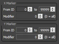
X Marker/Y Marker
Allows you to filter which Marker IDs and Modifiers generate Marker segments
From/To ID
allows you to set a range of marker IDs. Any markers with IDs outside this range are ignored.
Modifier
When using multiple RC Spline modifiers it is possible to limit a generator to use just one. The index is counted from the top of the modifier stack downwards. Setting this value to 0 will allow RailClone to use markers in all the RC Spline modifiers applied to a path.
Limits
Sometimes it is necessary to combine several generators in a single RailClone object, applying each one of them to different parts of the same spline. This is achievable using Limits which are defined here.
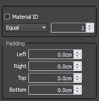
Material ID
Only applies the generator to the spline's segments with the material ID specified. To define a material ID in a spline, use Editable Spline>Sub-object Segment>Surface Properties>Material. Acceptable
values are single numbers, ranges and multiple entries separated by commas. For example: "1,3,5-8".
If this is used with Extend X/Y size to area mode,
the ID of spline's first section is used.
Padding
Adds an offset to the left, right, top and bottom of the generator. All calculations, such as evenly spacing, are based on the new lengths of the array after the offset has been applied.
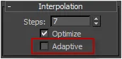
Occasionally when using the Limit by Material ID option of a generator to restrict geometry to a particular section of a spine, it is generated incorrectly. This is often caused by using Adaptive mode, found in the spline's Interpolation roll-out, which can scramble the material IDs. If this issue occurs, simply turn off Adaptive mode to restore the correct behaviour.