Segments
Overview
Segments are the basic building blocks that are assembled to create a RailClone object. You can assign any object or group from the scene, including non-geometric objects like lights, as a Segment. Once assigned, the segment's geometry becomes part of the RailClone object, and you can handle it at the sub-object level (when its node is selected in the Style editor). Source Geometry can be deleted once assigned because RailClone stores an internal reference to its mesh. It works in a similar way to 3DS Max's compound objects (such as Boolean), working in "Instance" mode.
The segment node allows you to control the following parameters, click on a heading for the related reference material or follow the procedures for instructions on how achieve specific results.
- Padding: Allows you to adjust the default size used to calculate the position of adjacent segments
- Fixed Size: Allows you to specify a size for the segment in scene units. Works in two modes. In Calculation Mode the segment's geometry remains unchanged and dimensions affect only the positioning of adjacent segments. Or Scale node where the segment's geometry is rescaled.
- Alignment: Controls how the segment is aligned to base objects.
- Deformation: Controls how a segment bends along the base object path and the vertical distortion to create vertically aligned, stepped and adaptive effects.
- Mapping: Provides the ability to use box mapping across a number of adjacent segments, creating seamless, unbroken textures.
- Transforms: Set either fixed or randomised rotate, transform, and scale parameters for segments.
- RailClone 5 includes native support for instancing lights in V-Ray 2.1 and above
- There is currently no native support for other renderers. As a workaround, objects are inserted in the scene before rendering and removed once completed.
- The size of some non-geometric objects may not be reliably read by RailClone, or it may change depending on the active viewport. If it affects your style, we recommend using the Segment's Fixed Size feature.
- Non-geometric segments are previewed as boxes in the viewport with a Material ID defined in the Display->Non-geom "Mat.ID" parameter
Procedures
To add objects (geometry, lights etc.)
-
Create a new Segment Object () by dragging from the Items List to the Construction View.
-
Go to the Properties Editor and click on the Object picker.

-
Select the geometry you wish to use from the scene. 4. Wire the Segment node to an appropriate Operator or Generator input
To add Groups
- Create a new Segment Object () by dragging from the Items List to the Construction View.
- Go to the Properties Editor and click on the Object picker.
- Middle Click in the scene to return the focus to Max
- Press H on the keyboard to open Selector by Name
- Pick a group.
- Wire the Segment node to an appropriate Operator or Generator input
Groups cannot be 'embedded' within an RailClone object. When a Group is deleted from the scene, it's removed from RailClone as well.
To add multiple segments
-
Create a new Segment Object () by dragging from the Items List to the Construction View and add geometry as described in the previous procedure. Enter the general, deform, or transform settings required for all segments before going any further. This node will be used as the template for other segments added using this technique.
-
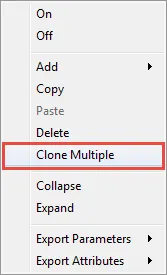
Right-Click on the new Segment and select Clone Multiple.
-
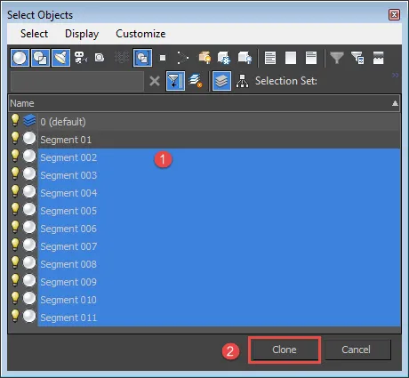
A Select Objects window opens. Pick the objects in the scene you wish to add to the RailClone style and click Clone, RailClone will generate a new Segment node for each of the selected items
To update geometry
When editing segment geometry referenced in a RailClone object, certain operations do not automatically update. This is because some actions, such as converting to an editable poly or mesh, create new geometry in place of the source object. If this happens the RailClone object will use the original mesh and further changes will not be automatically updated, this is normal and 3DS Max's compound objects work in the same way.
- In this situation, to update the geometry reference with the new source object, use the Reload button () in the Style editor.
- You do not need to do this for each segment node. The refresh button will operate on all Segment nodes in the current Style.
To delete source geometry
Once geometry has been added to the style via a segment node, the original source mesh can be safely deleted. Though it is not necessary to do so, this may make the sharing and archiving of styles simpler.
- Add geometry to the style as described above.
- Select and delete the original source geometry.
- Segments that have had their source geometry deleted will display " --embedded--" in place of the object name.
- To re-extract geometry from a RailClone object, see the next procedure.
To extract segment geometry into the scene for editing
Once a segment is assigned it is possible to delete the original geometry as the RailClone object stores a copy of the mesh internally. However, on occasions it may be necessary to extract this Geometry back into the scene.
- Select the segment node you wish to extract.
- Click the Extract Segment To A New Object button () from the toolbar or go to Segments>Extract from the menu.
- The Segment will be created in the scene at its original coordinates.
To overlap or add spaces between Segments
Segments calculate a default size based on the dimensions of the source geometry's bounding box. The padding values allow you to overlap or add spaces between adjacent objects by adjusting this size.
-
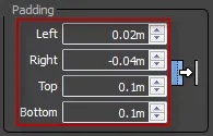
To change the alignment of an object to the left or right of the current segment, adjust the Padding>Left or Right values. A negative number will overlap the adjacent segments, a positive will create a space between them.
-
If you are using an A2S generator, use the Padding>Top or Bottom values to adjust the spacing above and below the current segment. As before, a positive value will create a space and a negative will create an overlap. See the padding reference below for a more detailed explanation.
To rescale geometry to a specific size
There are two ways to resize a segments. Either use the scale factor in the Transform properties, or enter a specified measurement in scene units in the Fixed Size settings
-
Select a Segment and open the properties panel.
-
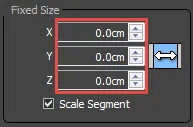
From the General > Fixed Size droperties, enter a value in the Z. Y or Z inputs boxes.
-
Turn On Scale Segment. To export the values, right-click on the node and select Export > Fixed Scale > X/Y/Z.
-
Wire a new Numerical node to the exported property, set the mode to scene units. You can now adjust the size of the segment from the properties rollout in the modify panel.
To bend segments to follow the spline paths
-
Ensure that source geometry has a sufficiently dense mesh for smooth deformation. For 1LS you will, may need horizontal subdivisions, for an A2S you may need both horizontal and vertical subdivisions if both splines are curved.
-
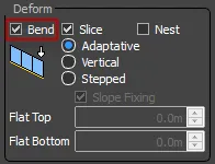
Go to Segment Properties>Deform>Deform and turn on Bend.
To create stepped segments
-
Select a segment you wish to set to stepped.
-
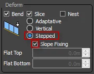
Go to Properties>Deform>Deform> and change the mode to Stepped. To vertical deformation will be applied to this segment when used with an L1S generator.
-
If you would like the segment width to remain the same as the source geometry when measured on the horizontal axis, ensure Slope Fixing remains on. If this option is switched off then the width will be measured along the angle defined by the path spline.
To create segments with upright verticals
-
Select the segment you wish to vertically deform
-
Go to Properties>Deform>Deform> and change the mode to Vertical. The segments will now deform so that the horizontals follow the path but the verticals remain upright.
-
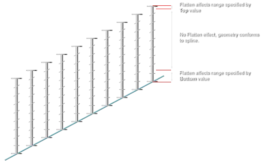
Enter a value into the Flat Top or Flat Bottom parameter boxes to maintain a stepped appearance for a part of the segment mesh. The value defines an area of influence, represented as a distance in world units from the top or bottom of the segment's height.
To randomise translation, rotation or scale
-
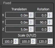
Segments can be transformed directly from within the Style Editor by going to Transform>Fixed and then adjusting the values for either Translation, Rotation or Scale.
-
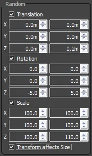
To randomise a Segment's position go to Transform>Random and turn on Translation. Each axis can be randomised independently by entering a Minimum and Maximum value, measured in scene units.
-
To randomise rotation, activate Transform>Random>Rotation and enter Minimum and Maximum values in degrees for each axis you wish to randomise.
-
To Randomise Scale, activate Transform>Random>Scale and enter Minimum and Maximum percentages for the axis you wish to randomise.
-
If you would like that transform setting to affect the height and width used to calculate the packing of adjacent segments, leave Transform Affects Size on. If you would like to retain the size of the original segment before transforms, switch this setting off.
To prepare geometry for use as segments
Though segments can be rotated and scaled from within RailClone, properly prepared geometry can save time. In particular, attention should be paid to the local axis. RailClone uses this to determine the alignment in relation to the Base Objects. The X axis of the geometry will be aligned with the path direction while the Y runs perpendicular.
- If a segment is to be bent along a path, ensure the geometry has a sufficiently high mesh density to allow for smooth deformation.
- If adjacent segment geometry is to appear seamless, ensure it has the same smoothing group allocated.
- Rotate and scale your segment geometry the way you wish it to appear in finished RailClone object, in relation to the world axes.
- Go to Hierachy>Adjust Pivot>Affect Pivot Only and then press Align to World.
- If necessary, adjust the location of the pivot. point.
- Go to Utilities>Reset XForm>Reset Selected. UVW map the object if necessary, alternatively simple box mapping can be applied automatically from with RailClone.
To Add Box Mapping to segments
Using regular repeating segments can result in obvious tiling of the textures. To help resolve this it is possible to turn on box mapping that uvw maps across several adjacent segments according a size set in the segment's Deform>Mapping settings.
- Select the Segment you wish to map and go to Properties>Deform>Mapping. Turn on Box Mapping. Either set the size of the box map using the Length. Width and Height settings, or if you are using materials with real world map size settings, simply turn this option On.
- Use the Rotation parameter to align the map correctly on the segment.
- Set the UVW channel to target, using the Map Channel spinner.
Interface
Object
Displays the name of the geometry object in the scene associated to the Segment. To assign, click this box then pick from the Max scene.
Once the geometry has been assigned the original source mesh can be deleted from the scene. RailClone stores a copy of the geometry locally, in a similar fashion to 3DS Max's compound objects working in instance mode (such as Pro-Boolean). If the original object has been deleted the word --embedded-- will display in place of the original object name.
Padding
Each segment has a defined length and height, which controls how it will be assembled with other segments along the paths. By default, this length is determined by the size of the bounding box of the source geometry. The Padding parameters allow you to modify the default size, increasing or decreasing the distance with other segments to the left, right, top and bottom sides.
Top and Bottom paddings are applicable only to the array generators, as 2D arrays - Generator A2S .
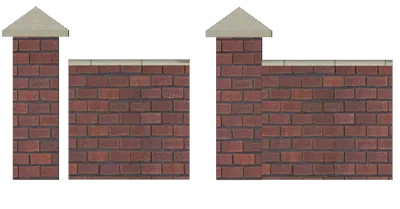 Applying a negative right padding to the Post segment makes it shorter, and fixes the separation created by the top piece
- The effective size of a segment on X is: geometry size + padding left + padding right, where padding values can be positive or negative.
- Padding doesn't modify the position of the segment on the path by itself (as the Local Transform->Translation parameters does), but how the surrounding segments (horizontally and vertically) must be adjusted.
Fixed Size
Use these values to override the dimensions for the segment. Turning on Scale Segment will re-size the segment to match the dimensions. This property can be exported, simplifying the process of parameterising the sizes of segments,
Alignment
These parameters help you to align the segment on the underlying path. Alignment can be defined for each axis, from the following values:
X: Automatic, Pivot, Left, Center, Right
Y/Z: Automatic, Pivot, Bottom, Center, Top
The Automatic mode, uses the best alignment mode depending on the Segment's position: for example, "Left" for Start pieces, "Right" for End and so. This is the default mode, and should work well for most of the situations, usually it is not necessary to change it. See table and illustrations below for an explanation of the values used when alignment is set to automatic. Depending on the generator type and input slot to which a segment is connected, the automatic alignment is as follows:
L1S
| X: | Start Left, Default Left, Corner Center, Evenly Center, End Right |
| Y: | All Segments= center |
| Z: | All Segments= bottom |
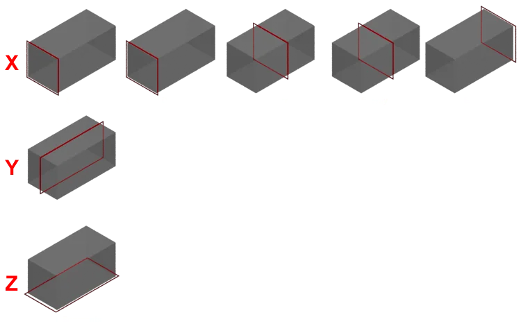 Default alignment for L1S Generator when set to Automatic
A2S
| X: | Start Left, Default Left, Corner Center, Evenly Center, End Right |
| Y: | Bottom Side Bottom, Default Bottom, Evenly Center, Top Side Top |
| Z: | All Segments= Bottom |
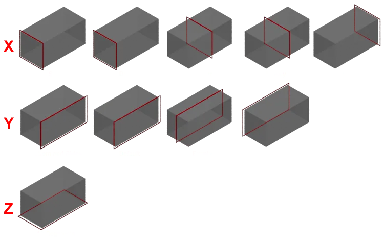 Default alignment for A2S Generator when set to Automatic
RailClone uses the local coordinates of the segment object. The same geometry would generate different results, depending on the rotation of its local pivot. It's a good habit to apply "Adjust Pivot->Align to World" and "Utilities->Reset XForm" before assigning an object as Segment.
Deform
These parameters define how RailClone must deform the segments to follow the trajectory of the path.
Bend
If enabled, the segment is bent along the path. If not, RailClone places the segment on its position in the path without applying any horizontal deformation.
 Applying bend on curved walls
When working on curved paths, besides enabling the Bend feature, be sure your segments have enough horizontal subdivisions to get a smooth result. RailClone does not subdivide the segments automatically.
Slice
Allows RailClone to slice the segment if it doesn't fit in the path. This feature is especially useful when creating objects such as railings or walls.
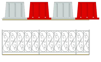
Nest
A legacy feature used to support RailClone 1.x styles. If a Railclone object is used as a segment within another, this feature allows paramaters to be randomised each time an item is used. In most situations an A2S generator will achieve equivalent results without the need to nest multiple RailClone objects.
Force Instance
When enabled, a Segment is always instanced on rendering.
Instanced segments cannot be bent or sliced, and Z Deform is restricted as well.
Z Axis
One of the most advanced features of RailClone is the ability to build complex structures such as railings or walls along sloped paths. The following options define the behavior of the segments in these cases.
Adaptative
The segment is aligned to follow the tangent of the path.
Vertical
The geometry stays vertical, but the vertices are moved in the Z axis to match the elevation of the path.
Stepped
No deformations are applied in the Z axis, and the segment preserves its vertical alignment.

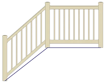
Usually, in complex structures such as railings, you need to use different Z Axis options for each type of segment. In the following example, the handrail is built using three segments: post (stepped), joint (stepped) and picket (vertical).
Slope fixing
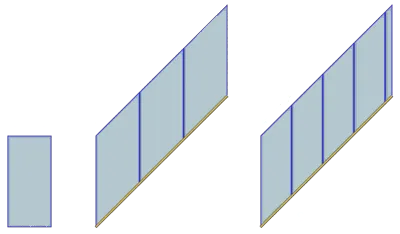
This parameter adds a correction to the segment's size to compensate for the inclination of the path. It is used only for Vertical and Stepped modes, and it's enabled by default.
Flat Top/Flat Bottom
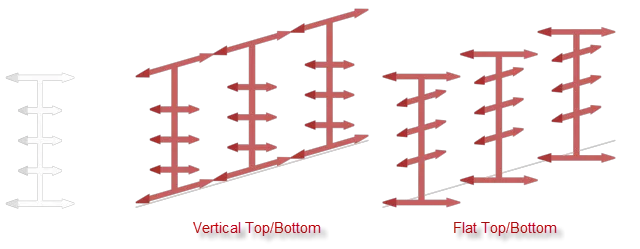
Working in Vertical mode, these parameters allow you to flatten the top or of the bottom of a geometry. The values define the maximum distance (in Z axis) that the effect is applied, starting from the top or the bottom of the geometry. This feature is especially useful for railing posts, and works as a combination of Vertical and Stepped modes in the same segment.
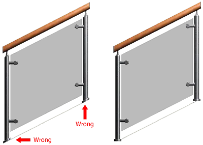 Flat Bottom used in a vertical post of a handrail structure
Vertical Top/Bottom
When using Stepped mode, these parameters enable the top or bottom of a segment to deform and follow the spline, leaving the area middle area stepped. The two values define the distance (on the Z axis) to which the effect is applied, starting from the top or the bottom of the geometry. The illustration below demonstrates the differences between Vertical Top/Bottom and Flat Top/Bottom.
Mapping
Generates UV coordinates of type "Box" to the segment. Instead of using the default UV coordinates of the individual segment, this mapping is seamlessly tiled along the full length of the RailClone object.
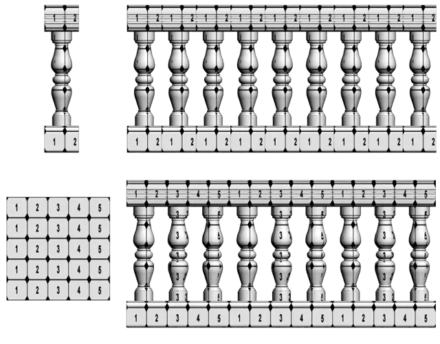
Apply Box Mapping: turns on RailClone's automatic box mapping mode
Real-World Map Size: turn on to use with materials set to use Real-World Map Size for tiling.
Length, Width, Height: sets the dimensions of the box map.
Rotation: rotates the UVW mapping, equivalent to rotating the texture on the W axis.
Map Channel: inter a map channel to apply the box mapping, to map multiple channels enter them as a list separated with spaces.
This feature is available only in V-Ray, when Display->Instancing Engine is enabled. See Best Rendering Practices for more information about the rendering modes.
Fixed Transform
Applies the specified transformations of translation, rotation and scale to the segment.
This behaves differently from version 1.x. In RailClone 2.x the alignment options are applied AFTER the fixed transform. This behaviour is more natural, but would generate significant differences when using objects created with previous versions.
Random Transform
Lets you apply random translation, rotation and scale transformations. They are applied in the local coordinates of the segment.
Transform affects Size
When enabled, RailClone consideres the random transformation to compute the size of the resulting segment. If disabled, the size is fixed (based on the original geometry without random transforms).
 A roof using tiles with random rotation and scale. Tiles are misaligned if Affects Size is on
RailClone uses an approximation algorithm, to get the size of a random transformed segment. The result would be less precise, compared with the same transformation applied as "Fixed". For example, between using a Fixed Z rotation of 90º, or Random rotation of 90º to 90º.