Creating Conditional Relationships
Sometimes you may want to swap segments dynamically based on other conditions in the array. For example, you could create a truss that increases in depth as the length gets longer, or a corner segment that changes depending on the angle.
Using the Conditional operator you are able to change segments based on spline length, the segment's position in the array, whether the spline segment is a curve or a line, the segment count on the X and Y axis, and the splines segment's material ID. Best of all, t
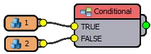
he Conditional operator is very easy to use, it takes two segments as inputs and only returns one of them depending on whether the test conditions return true or false.
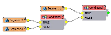
If you want to test for multiple conditions, nodes can be nested to create a more complex decision tree. There's no limit on the number of conditional operators that can be connected in a chain, so complex relationships are easy to set up and use.
In this chapter we'll look at how to use the Conditional Operator's parameters using a Ducting example. To get started,
load chapter_9_ducting_start.max from the downloads
for this tutorial.
Spline based Conditions
Exercises
The first 4 exercise explore the ways in which the conditional operator can be used to test attributes of the spline path.
Exercise: Creating conditions based on spline length
Using the Conditional operator you can use different segments based on the length of the spline or spline section. Though this is only a small part of what this operator is capable of, even this small subsection of conditional rules provides a lot of options. The following four steps demonstrates a simplified generic procedure for creating conditional setups using the length parameter.
- First of all, you need to turn on the condition which you want to test. Only one can be activated per Conditional node, so if you want to test more than one condition you'll need to connect multiple nodes as shown above.
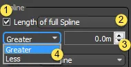
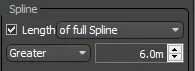
- Choose whether you want to check the length of the full spline or just the length of the current spline segment.
- Enter a Length measured in scene units.
- Choose whether you want to return True if the current spline or segment length is greater or less than the length value.
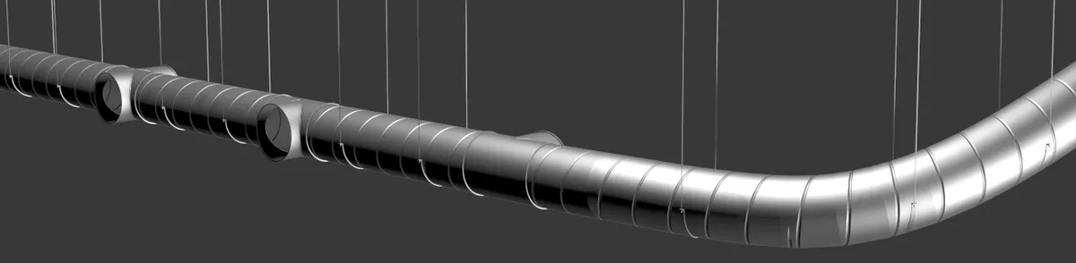
In the first ducting example, we'll look at how to change the size of the pipe based on the length of the spline.The scene has been set up with all the necessary segments, all we need to do is add and configure the conditional operators.
-
Select rc_spline_length and open the Style Editor
-
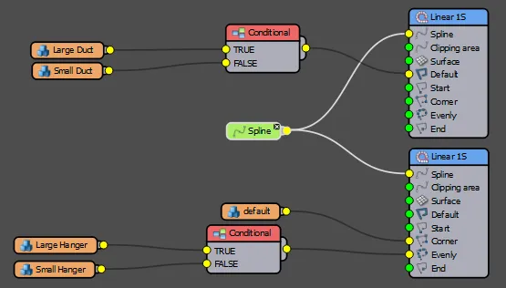
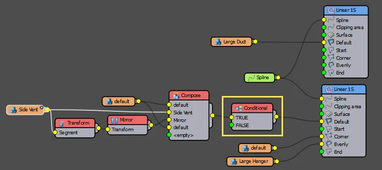
There are two Generators, one for the pipes and another for the hangers. Each of these has a small and a large size segment. For each generator, create a new Conditional operator and wire the Large segment to the True input.
-
Connect the Small segments to the Conditional operators False input.
-
Connect the Duct's Conditional operator to its Generator's Default input and the Hangers Conditional operator to its Generator's Evenly Input. At this point the graph should look like this:
-
For both Conditional operators, turn on Spline > Length from the Properties Panel
-
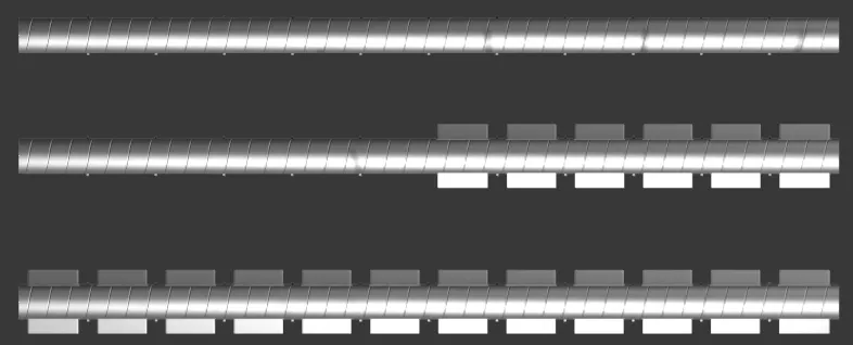
Enter a Length value of 6m and change the dropdown list to Greater.
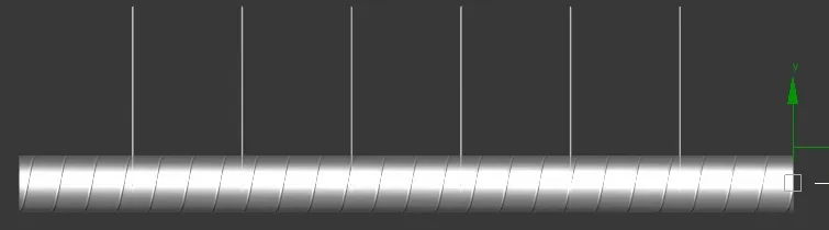
-
These conditional operators will not return the large version of the ducting if the spline is greater than 6m, and the smaller version if it is less than that.
Exercise: Creating conditions based on the segment's Position on the X or Y spline
As well as being able to test the overall length of the spline or spline segment, you can also use the Conditional operator to test a Segment's position on the spline or spline section. To use this feature you can follow these steps.
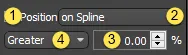
- Turn on Properties > Spline > Position. Make sure no other checkboxes are ticked.
- Choose whether you want to check the length of the entire spline or just the length of the current spline segment.
- Enter a position value to test for, this is measured as a percentage of the current spline or spline section's length.
- Choose whether you want to return True if the current spline or segment length is greater or less than the position value.
To see this in action, in our ducting example we'll add some side vents but prevent them from appearing in the first and last 20% of the path.
-
Select rc_spline position and open the style editor.
-
This example features two generators. One for the ducting, and a second one for the vents and the hangers. In this exercise we only need to worry about the vents which are wired to the second generator's Default Input.
-
Wire a new Conditional operator between the existing Compose operator and the Generator's Default input. Make sure the Compose operator is wired to the Conditional operator's True input.
-
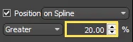
Select the Conditional operator and turn on Properties > Spline > Position.
-
Set the Percentage value to 20%. Leave the other defaults as they are.
This will prevent the vent from appearing within the first fifth of the spline. Next lets prevent them from appearing in the final fifth by connecting multiple Conditional nodes in sequence.
-
Create a new Conditional node and wire it between the existing Conditional node and the Generator's default input. Make sure to connect the nodes via the True input.
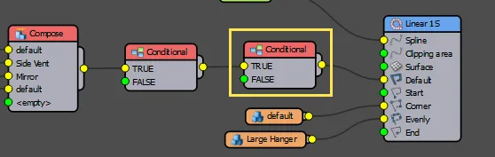
-
Select the new Conditional node and turn on Properties > Spline > Position.
-
Set the Percentage value to 80%.
-
Change the dropdown menu to Less
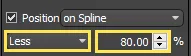
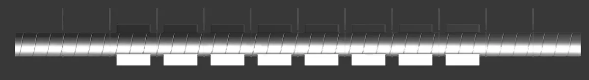
This conditional operator will only return true if the current segment is within the first 80% of the spline's length. When combined with the first Conditional operator we will now only get a vent segment if it falls within 20% - 80% of the spline's length.
Exercise: Creating conditions based on the type of spline segment
In addition to the length of the spline and a segment's position along the path, RailClone can also test to see if the current spline section is a straight line or a curve. This can be extremely useful if you want to optimise your models as you can use a higher resolution mesh on curved paths so that it bends smoothly, and a lower resolution on straight paths where no deformation is required. To use this feature, follow these steps:
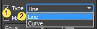
- Turn on Properties > Spline > Type. Make sure no other checkboxes are ticked.
- Select the type of spline segment that will return a True result from the drop-down list.
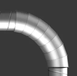
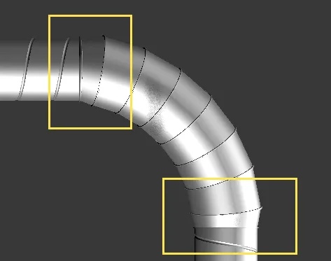
In our ducting example, we'll use this feature to create an articulated section that is used only on bends, with a transition at either end to compensate for the slight change in diameter. Here's how
-
Select rc_spline_type and open the Style Editor.
-
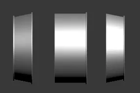
As in the previous examples, this style features two generators. The first is used for the ducting, and the second one is used on for the hangers. In this example we only need to worry about the first generator. There are also 3 additional segments for the curved sections of the spline. These are called bend start . bend mid , and bend end.
-
Let's start with the Default segments. Create a new Conditional operator and wire the large duct segment to the True input. Wire the condition operator to the Generator's Default input.
-
Wire the "bend mid" segment to the False input.
-
Select the conditional operator and turn on Properties > Spline > Type. Change the Type drop-down to Line. You will now have a different segment on the curved part of the spline.
-
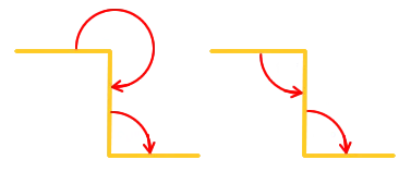
In the next steps we'll add a transitional segment between the straight and curved sections using the Generator's Corner input. When using Conditional operators with the Corner input, an important thing to understand is that the corner uses the spline section that precedes the vertex to determine the type. So in the corner pictured above when viewed from left to right, the first corner is of the type Line, because a straight section immediately precedes it, whereas the second corner is of the type Curve, because it is preceded by the arced section of the spline. We can use this to our advantage to create intelligent corners that add a different segment when they are at the beginning and end of a curved or straight section of spline.
-
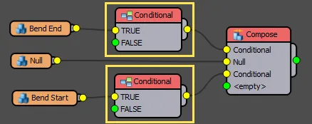
The existing style has a compose operator for the corner segment. Add two new conditional nodes, each between the existing segments and the compose operator.
-
Select the Top conditional operator and turn on Properties > Spline > Type. Change the type to Curve this will ensure that this segment only appears on the second corner.
-
Select the bottom conditional operator and turn on Properties > Spline > Type. Change the type to Line this will ensure that this segment only appears on the first corner.
-
Connect the Compose Operator to the Generator's Default input. You will now have a section with a ramped transition at the corners, between the two sizes of default segment.
Setting spline segment types
Whether a spline section is considered a line or a curve is not determined automatically, it must be set manually by the user. By default, most spline objects in Max are created with segments set to the type "Curve". To set the spline segment type property on a spline used as a base object, it is necessary go to the segment sub objects of an editable spline, choose a segment, right click to set as either a Line or Curve.
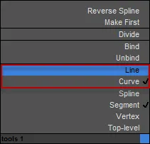
Right click to set the segment type of spline
Exercise: Creating conditions based on Spline Segment's Material ID
A great way to control which segments are used on a spline is by using Material IDs. Editable Spline objects can have material IDs applied to their segments that can be used in RailClone with the Conditional operator to create a number on interesting effects.To use material IDs you will need to do the following:
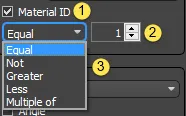
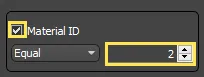
- Turn on Properties > Spline > Material ID.
- Choose a Material ID.
- Choose whether you want to return True if the current spline section has a material id that is equal, not, greater than, less than, a multiple of the Material ID value.
Setting Material IDs
To set the material IDs on a spline follow these steps.
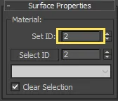
- Change the object to and Editable Spline or add an Edit Spline modifier.
- Go to segment of spline sub-object level and select the parts of the object you wish to change.
- Go to the Surface Properties rollout and enter a value for the Set ID parameter
In the example file, the base spline being used by rc_mat_id_conditional is divided into two material ids as shown below.
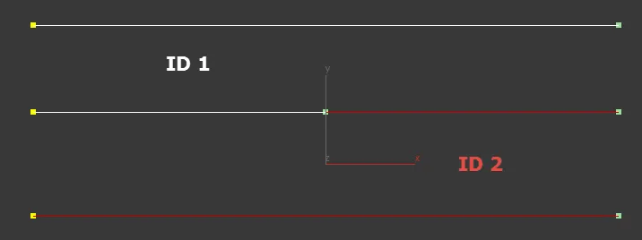
We can use this so that vents are only applied to the spline segments with an ID of 2 using the Conditional operator. Here's how:
-
Select rc_mat_id_conditional and open the Style Editor
-
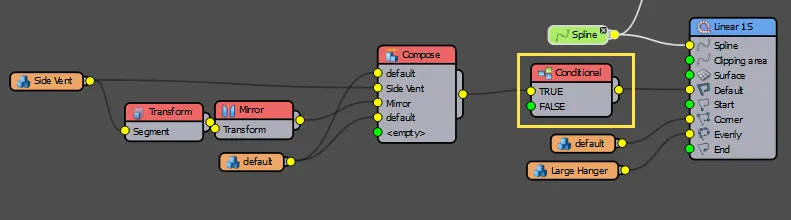
Create a new Conditional operator between the existing Compose node and the second Generator's default input.
-
Turn on Properties > Spline > Material ID.
-
Set the Material ID value to 2. You will now have vents only on the spline segments with the same ID.
Other techniques for creating conditional rules based on material IDs
Using the Selector Operator
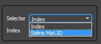
This is not the only way you can create conditional relationships based on material IDs. The Selector operator has a mode that allows you to derive the index value from the spline's material ID. To activate it just change the Selectordropdown to Material ID.
To set up the previous example using a Selector operator instead of a Conditional, try the following:
-
Select rc_mat_id_selector and open the Style Editor
-
Create a new Selector operator and wire it to the Generator's Default input.
-
Wire a new Empty Segment to the Selector node's first input.
-
Wire the Compose node to the Selector node's second input
-
Pick the Selector node and change Properties > Index to Spline Mat. ID.
-
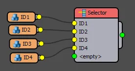
You will now have the same result as though you'd used the conditional operator. In this example there is little advantage to using this technique, but in the event of using multiple IDs the Selector operator can create the same effect as the conditional operator but with fewer nodes. For example, if you wish to use four segments and apply them to only 1 of 4 material IDs, the conditional node tree would look like this.
However, using the Selector Operator in Material ID mode it would be much simpler:
Using a Generator's Limit by Material ID features
As well as the conditional operator, it is also possible to limit the whole generator to use sections of the spline path based on the Material ID. To do this you use the Generator's Limit By Material ID options. This tells the generator to only create geometry if the spline section matches or is less than, or greater than an ID value. It is slightly different from the previous two techniques because each isolated section with a continuous unbroken ID is treated like a separate spline with its own Start and End segments.
This can be useful for breaking a continuous spline into sections, each with the possibility of using the full range of a generator's inputs. You can see an example of this in the Drop Kerb tutorial. In our ducting example we'll just create the same effect as the Selector and Conditional operator shown above.
-
Select rc_mat_id_gen_limits and open the Style Editor.
-
Select the second Generator and turn on Properties > Limits > Material ID.
-
Set the Material ID value to 2.
The vents will only be generated on spline sections with an ID of 2.
Vertex based conditions
The next 2 exercises explore the ways in which the conditional operator can be used to test attributes of the spline's vertices.
Exercises
Exercise: Creating conditions based on the type of vertex
Using the Conditional operator, you can use the type of vertex to select different segments. In this mode, the Conditional operator will return the segment wired to the true input if the vertex matches a specified type, selected from Corner, Bezier, Bezier-Corner or Smooth.
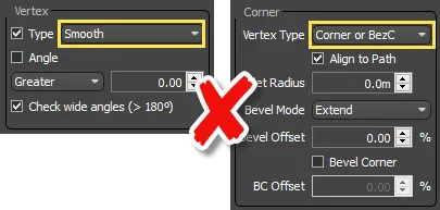
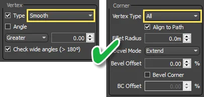
Of course for this to work you will also need to configure the generator to ensure that the specified vertex type will actually generate a corner segment. For example, if you have the Conditional operator to test for a Smooth vertex type, but the generator's corner settings are set to Corner or Bezier-Corner then it won't work because a corner segment will never be generated on a smooth vertex. Instead, you would need to change the Generator's Corner type setting to All to include vertices of the type smooth (as well as bezier, bezier-corner, and corner).
To use the Conditional operator to test for vertex types:
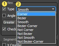
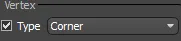
- Turn on Properties > Vertex > Type. Select the type of vertex to return true from the following settings: Corner, Bezier, Smooth, Bezier-Corner. Alternatively you can return true if the vertex is Not one of these 4 types.
- Ensure that the Vertex Type in the generator's properties includes the vertex type you are testing for.
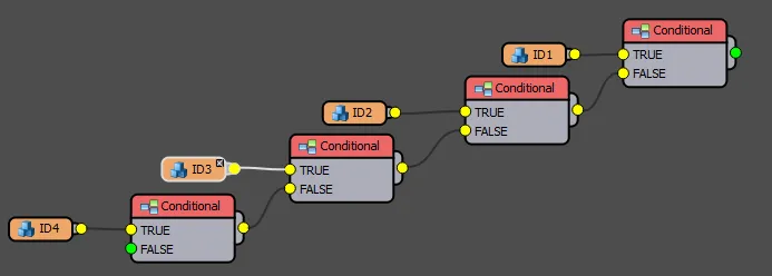
In our ducting exercise we will use vertex types to place 3 different types of joint, a branch right, branch left and an intersection. Because there are multiple conditions to test, we'll have to create a chain of Conditional nodes, each one testing for a different vertex type. To do this, follow these steps.
-
Select rc_vertex and open the Style Editor. There are 2 corner segments already in the style that need to be wired to the first generator.
-
Create a new Conditional operator. Wire the Joint 4 Outlets segment to the Conditional operator's True input.
-
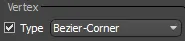
Select the Conditional operator and turn on Properties > Vertex > Type. Select Bezier-Corner from the dropdown menu.
-
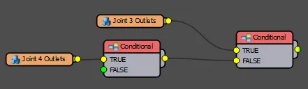
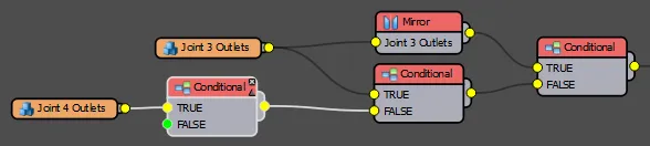
Create a second Conditional operator and wire the first one to its False input. Wire the Joint 3 Outlets segment to its True input.
-
Select the new Conditional operator and turn on Properties > Vertex > Type. Select Corner from the dropdown menu.
-
You know have an intersection created by smooth vertices and a branch right on corner vertices. To finish up we'll create a third Conditional operator to create a branch left segment. Wire the second Conditional operator to the third Conditional operator's False input.
-
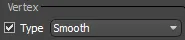
Select the third Conditional operator and turn on Properties > Vertex > Type. Select Smooth from the dropdown menu.
-
Create a new Mirror operator and wire the Joint 3 Outlets segment to its input. Go to the Mirror node's Properties and change the Axis to Y.
-
Wire the Mirror node to the third Conditional node's True input.
-
Wire the third Conditional node to the generator's Corner input.
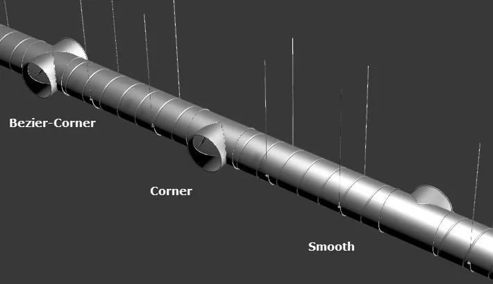
You should now have 3 different corner types shown along the length of the spline. Experiment with changing the vertex types on the spline to see the 3 Conditional operators in action.
The Vertex Type condition is usually used in conjunction a generator's Corner input to create different types of corners, as we saw in the examples above. However, it can also be used with the default input in which case the conditional node tests for the vertex at the beginning if the current spline section.
Exercise: Creating conditions based on the angle of the corner
As well as the type of vertex, the conditional operator can also evaluate whether the current corner is greater or less than a specified value. To use this feature use the following procedure.
-
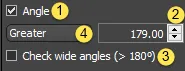
Turn on Properties > Vertex > Angle. Enter a value for the Angle parameter.
-
Choose whether the angle should be evaluated between 0 - 180 degrees or Wide chere the full 0 - 360 degree range is used.
-
Choose whether you want to return True if the current corner is Greater or Less than the Angle value.
In our ducting example we'll automatically remove the corner segments created in the previous exercises unless the corner in close to 180 degrees. This will allow for bevelled corners in addition to preformed junctions.
-
Continue with rc_vertex and open the style editor.
-
Add a fourth Conditional operator between the existing Conditional nodes and the Generator's Corner input.
-
Select the new conditional node and turn on Properties > Vertex > Angle.
-
Enter a value of 179 degrees in the Angle field.
-
Ensure Check Wide Angles is off.
You can now create bevelled and curved sections as well as adding 3 types of junction. Where a corner is less than 180 degrees, the junction segments are automatically disabled.
Segment based conditions
In the final section on the Conditional operator we'll look at how it can be used to test attributes of the array's segments.
Exercise: Creating conditions based on the segment count
The conditional operator can use the number of the current segment in the array measured against a fixed value to return one of two segments. It works by counting the number of segments on the X or Y axis and then returning true or false dependent on if the number is Equal, Not equal, Greater than, Less than, or a Multiple of a set value. To use this mode:
- Turn on Properties > Segment > X Counter or Y Counter. Enter a Count value
- Choose whether you want to return True if the current segment has an X or Y count that is equal, not equal, greater than, less than, or a multiple of the count value.
Using the Multiple-Of option, This operator can be used to create segments at certain intervals. In our air conditioning example we will exploit this feature to change the spacing of the side vents along the ducting. To do this:
- Select rc_segment_count and open the Style Editor.
- Wire the existing Compose operator to the True input of a new Conditional operator. Wire the Conditional node to the Generator's Default input.
- Select the Conditional node and turn on Properties > Segment > X Counter.
- Set the mode to Multiple Of and set the value to 5. You will now get a vent in every other bay.
- Try experimenting with different values. You'll notice that only odd numbers work, this is because the vents and the hangers are alternating, so the hangers land on even numbers while the vents are on uneven numbers.
In this chapter each of these conditional tests has been created in a separate style for clarity, but of course there's
no reason why they can't all be combined. In chapter_9_ducting_end.max you will find a style which combines many of
the exercises in this chapter. This style uses the following conditions:
- Vertex Type. Choose from 3 types of junction by using Smooth, Corner, and Bezier - Corner
- Material ID. choose to turn side vents on/off using Material ID 1 or 2
- Spline Segment Type. use line segments for regular ducting and Curves for articulated ducting.
- Segment Counter. used to change the spacing between side vents
- Selector Operator. Turn on and off the end grills.
Feel free to experiment and adapt this style to learn how many conditional nodes can work together to create a highly adaptive style.

Using the Selector Operator to create conditional relationships
For more advanced usage, the selector operator can also be used to create conditional relationships. There are two ways of doing this. You can either use the operator's built in mode to assign segments based on the material IDs as demonstrated earlier in this chapter. Or you can export the Index value and use this in conjunction with the Arithmetic node to create more complex conditional statements based on built in variables.
Both these techniques enables you to create conditional relationships with fewer nodes than is possible with the Conditional operator, but using the arithmetic node also gives you access to some variables that are not available elsewhere. You can see a full list in Chapter 3 - Wiring and Attributes, but to explain how to use Expressions with the Selector operator we'll focus on just one - the Position on Y Spline attribute which cannot be accessed from the Conditional operator.
Exercise: Creating conditions using the Selector operator and expressions
The Arithmetic node is capable of creating conditional expressions using If statements. The syntax of an if statement is fairly straightforward.
if(p,q,r);
Where p is the condition that is being tested, q is the value that is output if the test is true, and r is the value that is output if the test returns false. It is also possible to nest If statements using this format.
if(p,q,if(p,q,r))
In practice, you may find it is much clearer to format the expressions so that the if statements are on separate lines, especially if you have a lot of them:
if(p,q,
if(p,q,
if(p,q,
if(p,q,
r))))
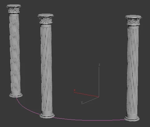
In this exercise we'll use this technique to add the top and bottom to a pillar which will have an adjustable height. This style is made from 3 segments in a two-dimensional array. The pillars will be added to the Evenly input so that we can easily control their spacing. To create this, follow these steps.
-
Open
chapter_9_pillar_start.maxfrom the download for this guide. -
Select the RailClone object and open the style editor. All the necessary segments have already been added to the style.
-
Create a new Selector operator.
-
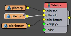
Next we'll wire the segments to the Selector operator's inputs. The order is important - the index numbering is built from the top of the list with an origin of 1. Wire the pillar top to input 1, pillar mid to input 2, and pillar bottom to input 3.
-
Wire the Selector node to the generator's Left Side, Right Side, X Evenly and Inner Corner inputs. Except the sides, none of these inputs have a way to target the top and bottom of the column, so we'll build an expression instead.
-
Right-click on the Selector node and Export the Index.
-
Create a new Arithmetic node and wire it to the Index socket. 8. Select the Arithmetic node and change the mode to Expression. 9. Open the Expressions editor and enter the following:
if(YSplinePosition=0,3,
if(YSplinePosition=1,1,
2))
As you can see, this is a nested If statement that is testing a segment's position on the Y axis. The position is measured from 0.0 at the start of the array to 1.0 at the end. The first if statement is testing to see if the segment is at the start of the spline (YSplinePosition=0.0), if it returns true then the expression outputs the value 3 to the Selector operator which picks the pillar bottom. If it is false then it tries the second If expression which is checking to see if the segment is at the end of the spline (YSplinePosition=1.0), if this returns true then the expression outputs the value 1 to the Selector operator which picks the pillar top. If this return false then it outputs a value of 2 which tells the selector operator to pick the pillar middle.
By using the if statement in the arithmetic operator in this way you are able to access many hidden variables in RailClone and create more sophisticated conditional relationships between parts without having to create a lot of additional nodes.
Related Tutorials
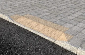
In this Tips & Tricks tutorial we look at how RailClone can be used to place drop kerbs using material IDs assigned to the base spline.

In this tutorial we explain how to use Conditional operators to test the position on a spline segment and prevent books from being created too close to the ends of a shelf where they might intersect with the vertical elements of a bookcase.
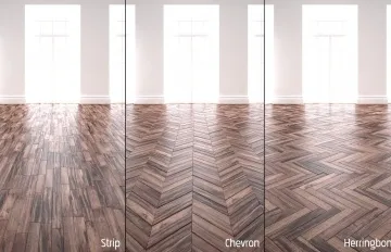
In this exercise we use the Conditional operator to create the pattern on the Strip floor. Using the conditional operator a half sized plank is added to the first segment in alternate rows to create an offset pattern on the floor.

In the spider glazing tutorial we show how to use the conditional operator to target parts of an array that do not normally have an input. By testing for a segments position and count on the Y spline, it is possible to add segments at the start and end of a column.
For more information please see the Operators . 1D arrays - Generator L1S , and 2D arrays - Generator A2S, sections of the online documentation.