How to Fine Tune Corners
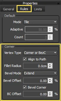
The L1S generator's Corner input and the A2S generator's Inner-Corner input allow you to position segments based on the vertices of the path. Though this seems straightforward, there are a number of controls to help you tailor your corners exactly how you need them. All the settings to control the behaviour of corners can be found in the generator's properties by clicking on the Rules tab.
Choosing the vertex type
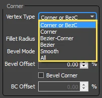
First of all, RailClone lets you decide which types of vertices are going to generate corner geometry. 3ds Max's spline objects have 4 types of vertex: corner, bezier-corner, bezier and smooth. In the generator's properties you can choose which of these 4 types creates a corner segment by simply selecting them from a drop-down list.
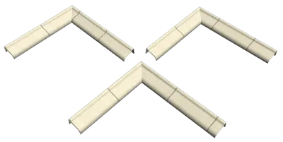
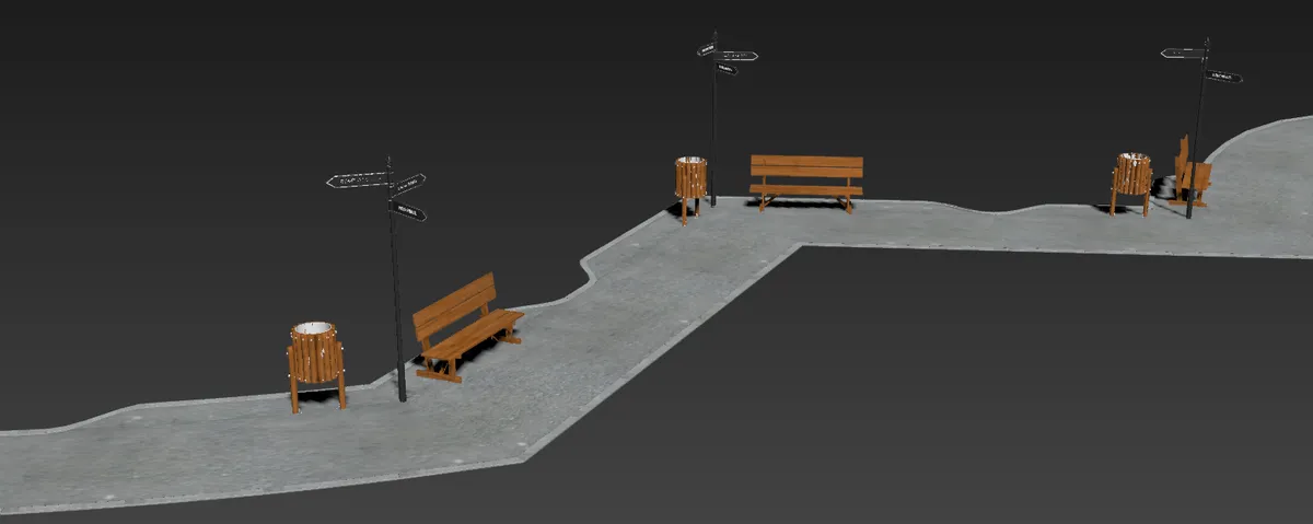
We'll look at an example to see how this works. In the following few exercise we'll create a style with a path, signposts, benches and bins to illustrate how RailClone handles corners.
Exercises
Exercise: Changing vertex types
-
Open
chapter_8_signpost_corner_angles_start.maxfrom the downloads for this guide. -
In this scene you will find two RailClone objects, a path and separate style for some sign posts. These could have been combined but to maintain compatibility with Lite users they have been separated for this tutorial.
-
Select the RailClone object called rc_signs and open the Style Editor. All the segments are already added to the graph, but nothing is wired up yet.
-
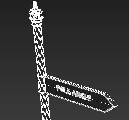
Wire the Post segment to the Generator's Corner input. This segment uses a simple pole with an attached sign. It has been oriented so the sign is perpendicular to the path.
-
You will now have a pole on every vertex on the spline of the corner or bezier-corner type. This is the default mode, but it can be easily changed from the Vertex Typedropdown found in the Generator's Properties > Rules menu.
-
To test these out try changing the Vertex Type to Smooth. You will now only have a single pole on the spline's sole smooth vertex. Change the type again to Bezier-Corne, and you'll see 3 poles, and change it back to Corner or BezierC and you get poles only on the hard bends, which is where we want them. Being able to select the vertex type in this way allows you to place Corner segments where you need them, but still enable you to use other vertex types to control the shape of the path.
Turning a Corner Segment's Bend setting On and Off
If you look at the poles you'll notice that they are deforming unnaturally.
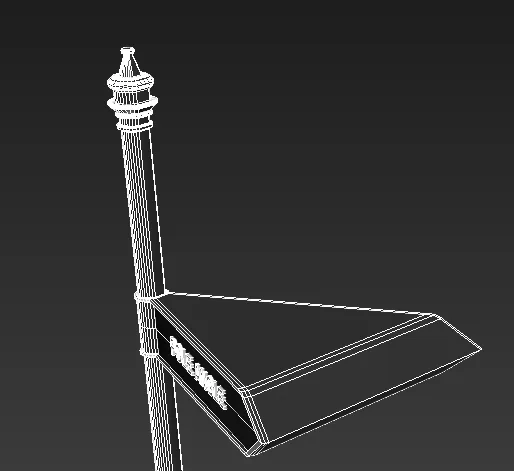
This is because RailClone's default behaviour is to try and bend the segments to follow the path. On a hard corner this can cause some issue so in many cases it is desirable to turn off the corner segment's bend setting. To do this follow these steps:
-
Select the Post segment
-
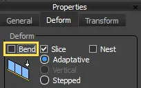
Select the Deform tab in the Segment's Properties
-
Turn off Bend.
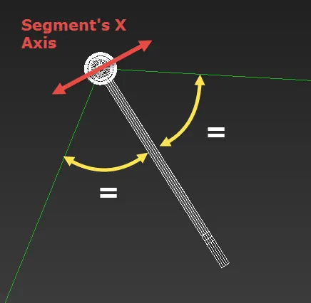
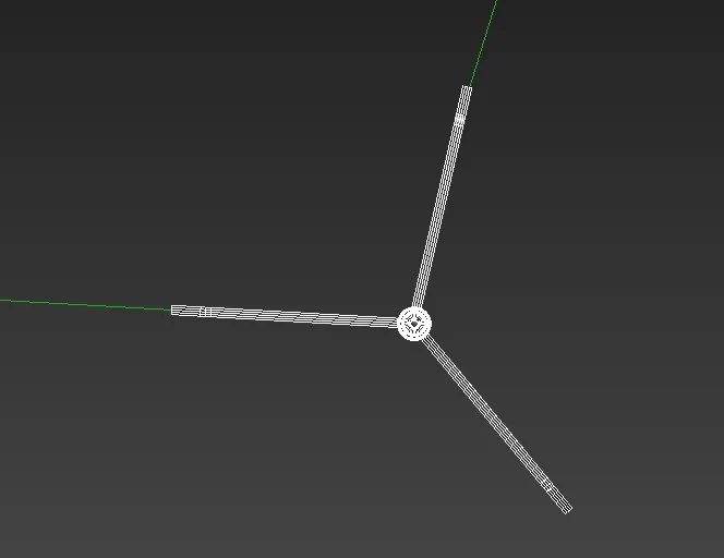
With Bend turned off the segments are no longer deformed to follow the spline and instead the segment rotates to bisect the angle of the spline.
-
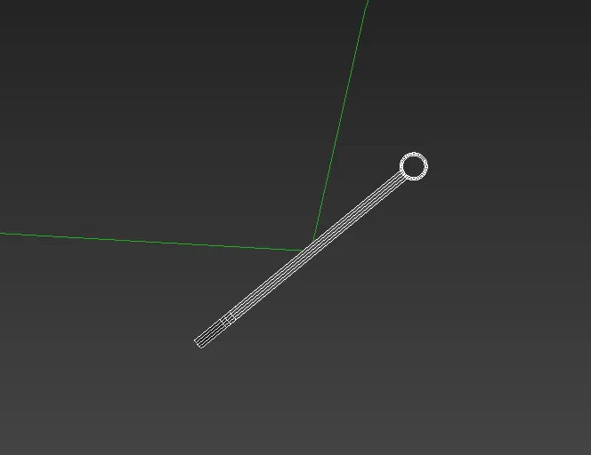
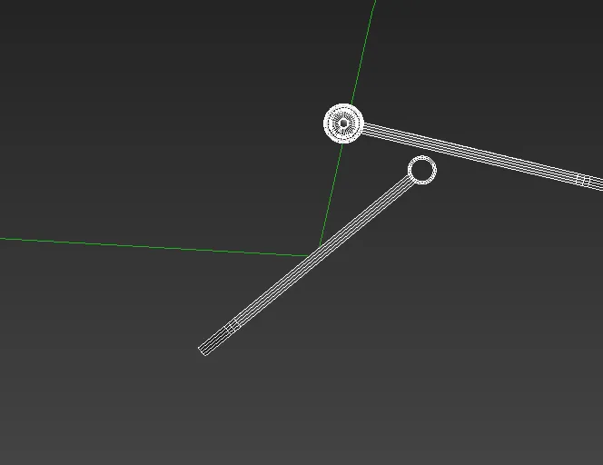
If you look at a top view you can see this; remember the sign was originally orientated so that it is pointing at a 90-degree angle from the path.
-
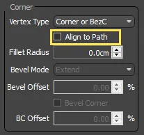
If you preferred that the corner segments did not rotate you also have the option to orientate the segment so that it is aligned with the precedingspline segment. To do this, go to the Generator's Corner settings and turn disable Align to Path
-
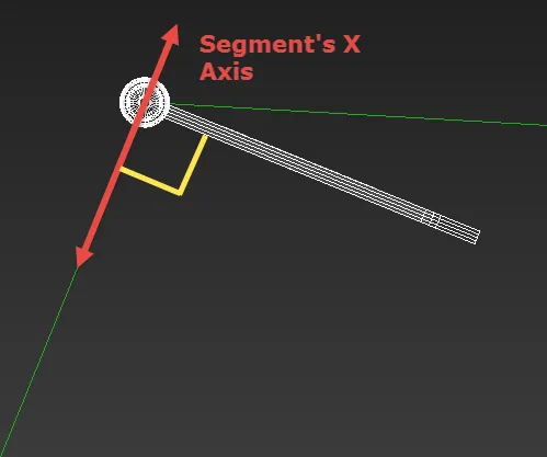
From the top view you will see that the segment's X axis is now in line with the preceding spline segment.
Turning off Align to Path is particularly useful for wall, railing and fence styles to correctly align a corner post that is square in plan. To see an example of this please see our introductory Masonry Wall tutorial.
Using the Compose Operator with Corners
When using a single corner input the segment's geometry is centred on the vertex. However, if you use the compose operator with the corner input slot, you will get different behaviour depending on whether you have an odd or even number of segments attached. In the next exercise we'll add the other two signs on either side of the post, and look at the behaviour of the corner as we add additional segments.
Exercises
Exercise: Composing Corner Segments
-
Continue from the previous exercise and add a new Compose operator to the generator's Corner input, replacing the post segment that was already there.
-
Wire the Start Sign segment to the Compose operator's first input. If you look at the style from the top view you'll see the expected behaviour as the sign is centred on the corner vertex.
-
Add the Pole segment to the compose operators second input. Instead of centring both segments to the spline, the first segment stays in the same place and the pole is added afterwards. This is because when using an even number of segments in the compose operator, RailClone centres the segment immediately before the vertex, then places other segments on the left or right depending on order in the compose operator. This means that using an even number of segments always creates an asymmetric corner composition.
-
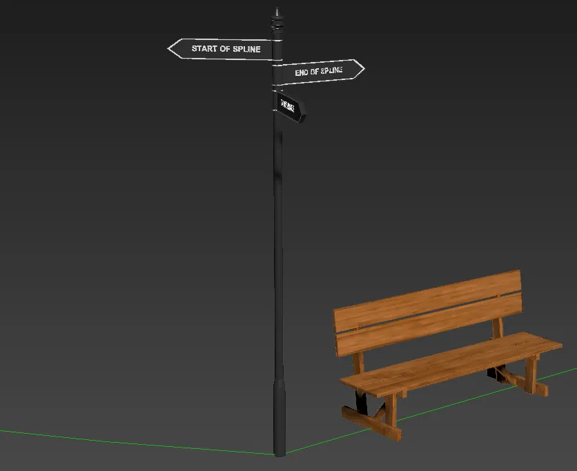
Add the End Sign segment to the Compose operators 3rd input. You now have and odd number of segments and the pole is centred on the vertex. When an odd number of segments is used, the middle segment is centred and the others are placed before and after this depending on the order in the compose operator. This means that using an odd number of segments always creates a symmetrical corner composition.
-
Let's keep going. Add the Bench Wood segment to the Compose operator. A bench is added after the signpost but nothing else moves. This is because this is once again an even number with no centre segment so instead RailClone picks the one preceding the middle, which is the post.
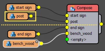
The other segments are placed either side of the post according to their order in the Compose operator
-
Finally, we'll add a bin to the first input slot of the Compose operator (using the up and down buttons to move it to the correct position -
 ).
Once again, there are an odd number of segments in the Compose operator so the middle is centred on the vertex.
You'll now have a pole on the vertex with a bin and sign before it, and a sign and bench after. You can also see that
the Align to Path controls only apply to the segment that is directly located on the vertex, the other segments
rotate to follow the spline section they are situated upon.
).
Once again, there are an odd number of segments in the Compose operator so the middle is centred on the vertex.
You'll now have a pole on the vertex with a bin and sign before it, and a sign and bench after. You can also see that
the Align to Path controls only apply to the segment that is directly located on the vertex, the other segments
rotate to follow the spline section they are situated upon.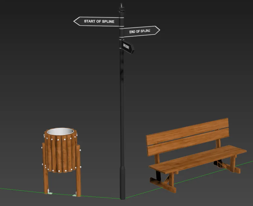
By understanding how the compose operator, Bend and Align to Path work together, you can achieve a high level of control to create sophisticated corner compositions.
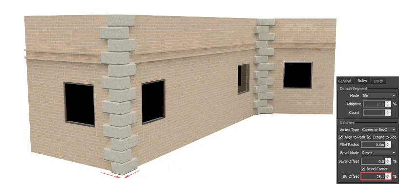
Bevelling Corners
If you need a seamless corner then segments can also be bevelled, slicing the geometry to ensure a perfect mitre. There are actually two sets of bevelling controls in RailClone, one for the default segments and another for the corners themselves. Default segments can be bevelled based on one of three rules.
- Reset. Each segment is placed in its default position, and simply sliced at the corner vertex.
- Extend: extends the geometry of the segments along the bevel, giving an appearance of continuity around the corner.
- Symmetric. Creates a symmetrical composition with the segment equalised either side of the Corner vertex.
In contrast, Bevelled Corners are simply sliced. The important thing to recognise is that though these two bevel operations have separate controls, they are in fact interrelated. Depending on the combination of their settings you will get different effects.The table below shows the relationship between the Bevel Mode and Bevel Corner settings.
| Bevel Mode | Bevel Corner On/Off | Default Segment Behaviour | |
|---|---|---|---|
| Extend, Symmetry or Reset | Off | Default segments ignore the corner geometry, continue to the corner and are sliced. The corner is deformed to follow the path. | 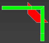 |
| None | Off | Default segments are sliced by the corner segment. The corner is deformed to follow the path. | 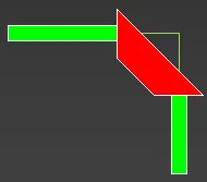 |
| Extend, Symmetry or Reset | On | Default segments stop at the corner segment. The corner is bevelled. | 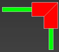 |
| None | On | Not possible, a bevel mode must be chosen to use bevel corner |
In the examples above we looked at the importance of understanding how the Compose operator works with Corner inputs. When using Bevel mode, more-or-less the same rules apply. The alignment of the geometry in relation to the Corner depends on the number of segments used in the Compose Operator. The illustrations below explain how using a single, odd or even number of segments affects the alignment when using bevel mode.
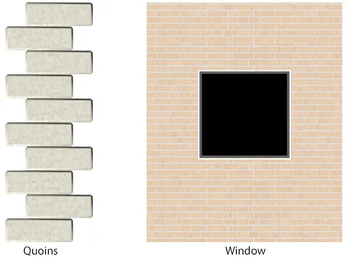
Segments used in this example
In the following examples these segments are used in the corner input. Where multiple segments are used, they are wired to a compose operator.
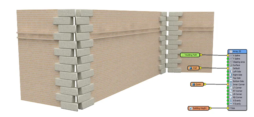
Using a single corner segment
Bevel mode works by duplicating the middle segment either side of the mesh and then slicing the intersection, this means that using a single segment in the corner input looks a little different with bevel on. The position of the pieces is adjusted to ensure that the full length, measured on the outside face and along the X axis, is maintained irrespective of the angle of the corner.
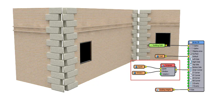
Using an even number of corner segments
When using an even number of segments, RailClone duplicates the segment immediately before the centre then places other segments before or after depending on their order in the Compose operator.
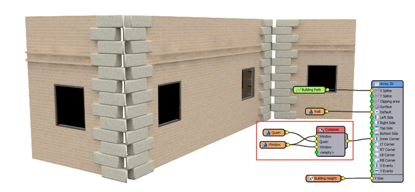
Using an uneven number of corner segments
When using an even number of segments, RailClone duplicates the middle segment then places other segments before and after depending on their order in the Compose operator.
Bevel Corner Offset
As you can see using Compose operators with Bevel Corner is similar to the exercise earlier in this chapter. The only difference is that the segment placed on the vertex is duplicated and bevelled. In the image above you can see a gap caused by the stepped pattern. To solve this you can use the Bevel Corner Offset parameter which allows you to adjust the slice point of the Corner segments. Distance is measured as a percentage of the length of the corner segment. Positive values pull the segment towards the corner, negative values will move the segments away from the corner. If a negative value is sufficiently large a gap will appear. The example below illustrates the effect of increasing the Offset value, bringing together and slicing the corner segments to close up the gap.
There are a couple of tips to get the most out of the Bevel Corners feature:
- The Bevel feature works better on straight lines and wide corner angles. You may get undesirable results on narrow angles or curved paths.
- When using closed paths, it's not possible to adjust the corner segment's offset on the last corner, because it depends on the path's length.
- Bevel is disabled when the Default Segment Mode is set to Adaptive or Count . We will look at a workaround for this later in the chapter.
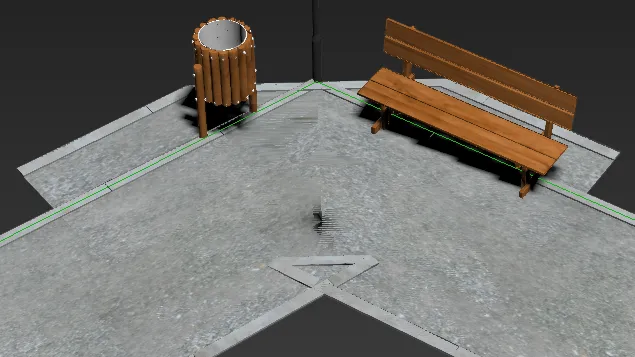
Exercise. Bevelling the Footpath
In this exercise we'll add composed corner segments to the footpath and use bevel to create a hard bend. The Corner segments are slightly wider than the main path to accommodate the bin, bench and signpost.
-
Continue working with
chapter_8_signposting_corner_angles.maxand select the rc_path object -
The Default segment is already wired-up and there are 3 corner segments ready to go. Create a new Compose operator and wire this to the Corner input
-
Wire the "Path Corner Mid" segment to the Compose operator's first input. The corners look like a bit of a mess as the segment is deformed around the corner and the default segments continue over the top.
-
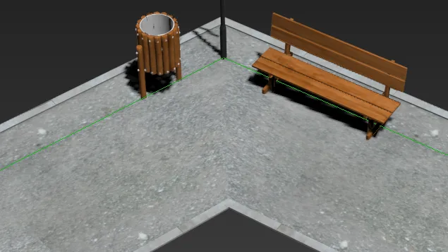
To fix this select the Generator and turn on Rules > Corner > Bevel Corner. The corner segment is now correctly bevelled and the default segments are sliced on either side.
-
To add the other sections, wire path_corner_start to the Compose operator and move it so that is in the first input slot. Then wire path_corner_end to the Compose operators third input slot. The corner is now complete and is neatly sliced with transitions between the wide and narrow parts of the path.
In the next section we'll look at how you can automatically turn hard corners into curves.
Automatically Create Curves with Fillet Radius
Endlessly filleting a spline corners can be a tedious activity, especially because once you've used Max's built-in fillet tool it's very hard to go back and change the size. RailClone makes this easy by allowing you to automatically adjust the corner vertices on a path to create rounded corners. The best thing is, this is fully parametric, so you can adjust it at any time. Here's how this feature works.
Exercises
Exercise: Using Fillet Radius
-
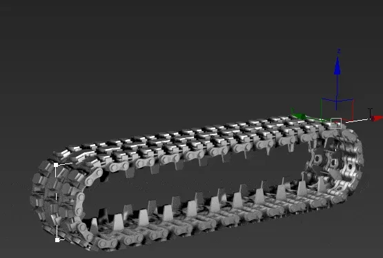
For this example we'll fillet the corners of a spline that is being used to generate tank tracks. Open
chapter_8_tank_tracks_start.maxfrom the downloads for this guide. You'll see a track style that is following a rectangular spline.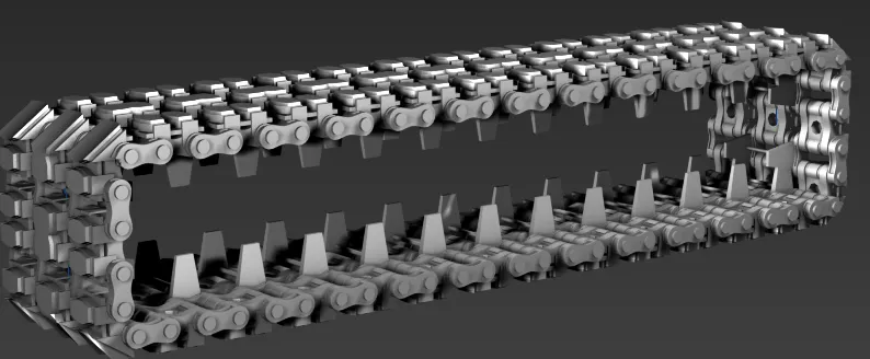
-
Select the Tracks and open the Style Editor.
-
Select the Generator. Go to the Rules tab in the properties and enter a value of 200cm for Fillet Radius. In this example I'm using a much larger value than is necessary. RailClone will use this as a maximum value and create the biggest fillet it can up to this size depending on the length of the shortest spline segment.
-
Try changing the size and shaped of the spline. You'll find the fillet automatically curves the corners while the spline itself remains very easy to adjust.
Note that when Fillet Radius is used Bevel Mode, Bevel Offset and Corner Bevel are disabled. This is because the spline is now curved and no longer contains sharp corners, so these settings don't apply.
Tip: Bevelling Corners in Adaptive or Count mode
Earlier in this chapter when looking at bevel mode we mentioned that this feature is not available when using Default>Adaptive or Count node. Though this is true, there is an easy workaround that allows you to use this two features together. To do this you split the style across two generators, one for the Default segments and a separate generator for the Corners.
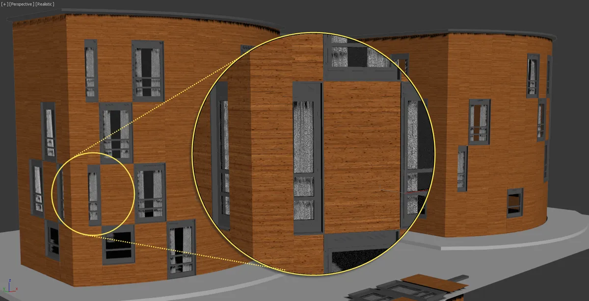
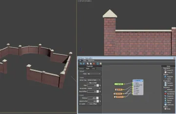
Take this façade for example, we want to bevel the corners, but we can't really use Default Tile mode otherwise we'll end up with sliced windows.But if we use Adaptive mode, which would be preferable, we can't get the bevelled corners.
To fix this, separate the style into two generators by following these steps.
-
Open
Chapter_8_adaptive_corners.maxfrom the downloads for this tutorial. -
Select the Façade and open the style editor.
-
To save some time we'll duplicate the existing A2S generator. Select the generator node, Right-Click and then select Copy. Right-Click again and select paste. You'll now have two identical generators. (Lite users can duplicate the RailClone object)
-
In the new generator, detach all the inputs except Inner-Corner. This generator will be used only to create these segments.
-
The A2S generator won't create inner corners unless there is something attached to the default input. So create a new Segment and wire it to the Default Input. There's no need to add any geometry to this node, it's just being used to trick RailClone into creating the Corner segments.
-
Go back to the original Facade generator and change the Default Tiling mode to Adaptive.
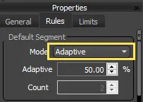
Now none of the segments are sliced, which is much better.
-
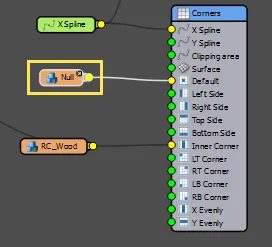
Now we need to create a gap at the corners for this style so that the other generators can fill in. To do this, wire a new Null segment to the Inner Corner input, replacing the existing connection.
-
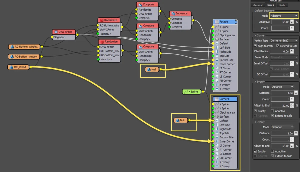
Select the Null segment and increase the Fixed Size > X setting until the corners and façade align correctly. 1.66m should do it. You now have the advantages of using adaptive default segments and levelled corners. Here's the final graph, changes have been highlighted in yellow.
Related Tutorials
The Masonry Wall demonstrates how to add posts to a simple wall style and control their rotation so that are correctly oriented for walls with 90 degree bends

Use splines to create power lines with a new pole added on each corner vertex.

In this tutorial we explain how to use RailClone to create a stone balustrade with posts added at evenly distances and on corners.
For more information please see the 1D arrays - Generator L1S . 2D arrays - Generator A2S , and Segments sections of the online documentation.