Master Spacing Modes
Many parts of arrays are placed precisely according to the base spline and size. For example Start segments are placed on the first vertex of a base spline, End Segments appear on the last vertex and corners can be placed on intermediary vertices of a particular type. There are however two types of segment that not placed with such precision, these are used to fill in between these set markers. Evenly segments are placed automatically at regular intervals on the X or Y axis of the array, and Default segments fill in any remaining spaces. Though distribution of these segments is automatic, RailClone has several useful rules to help you control the placement and scale.
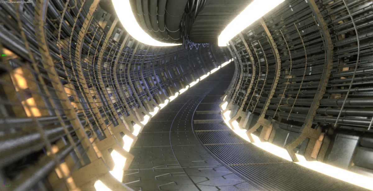
In this chapter we'll take a look at these parameters using a sci-fi corridor example. You can find this scene in the
downloads for this guide, the files is called chapter_7_spacing_modes_start.max from the
downloads.
This scene contains 7 RailClone objects. Each object is relatively simple in itself, but contributes an extra element to the corridor style which builds up to create a more complicated looking final result.
In the finished version, chapter_7_spacing_modes_end.max file, all the RailClone objects are combined into a single
style and the corridor can be controlled from the same interface and applied to a spline with single click. In the start
file each generator has been separated to individual RailClone objects to maintain compatibility with RailClone Lite.
In the start file all the generators use the default Tiling mode. Let's change these parameters to explore how the settings work.
Exercise: Exploring Evenly Spacing
Evenly segments are distributed at regularly spaced intervals along the X and Y axis. To control the distance between evenly segments you have two options, Count or Distance node.
Count node enables you to divide the spline path into a fixed number of evenly spaced segments. Let's try this out in the scene file.
-
Open
chapter_7_spacing_modes_start.maxfrom the downloads for this tutorial. -
Select the RailClone object called rc_walls (or rc_walls_lite if you don't have the Pro version)
-
Go to the Modify Panel, and apply the style to the flat_spline path from the Base Objects rollout
-
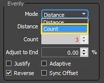
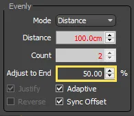
Open the Style Editor and select the Generator. Go to the Rules tab in the Properties Panel, and you'll find the Evenly settings at the bottom of the interface. Change the mode to Count.
-
Count mode divides the length of the path equally using the Count value. To change this you can edit it directly in the Style Editor, or you can export and attach a Numeric node, so it can be updated from the Modify panel. We've already exported this property, so go to the Parameters rollout in the Modify panel and enter a value of 5 for Evenly Count.
-
The path's length has been animated and if you scrub the timeline you'll see that irrespective of the length of the path, the number of evenly segment's remains exactly the same.
Alternatively you can use Distance node. When this is active the number of evenly segments is not fixed, instead segments are added at regularly spaced intervals along the spline separated by a measurement set by the distance value. As the length of the spline increases or decreases evenly segments are added or subtracted accordingly. To change the corridor walls to use distance mode, follow these steps:
-
In the Style Editor, change the Rules > Evenly node to Distance.
 .
. -
Change the Distance value to 150cm you can do this directly in the style editor or export the value and use a numeric node to make it editable from the Modify panel.
-
Now scrub the timeline. As the spline size gets larger you'll see additional evenly segments added to the array. Try different distance values to change the spacing between Evenly segments.
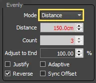
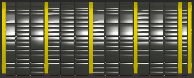
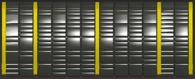
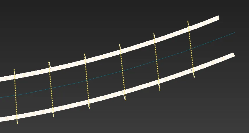
In distance mode you have 4 additional settings that control how evenly spaced segments are distributed along the spline. At its most basic, evenly segments are equally spaced at regular intervals starting from the beginning of the spline. This can result in an asymmetric distribution if the spline's length doesn't divide equally into the Distance value, as you can see in the example below.
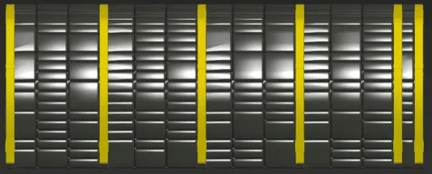
This is not always undesirable, and it is possible to change the direction of the distance calculation by selecting the Reverse checkbox. In the image below you can see the effects of this, notice now that the final evenly segment is now on the left.
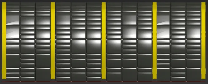
It is also possible to automatically create a symmetrical distribution of evenly segments using Justify node. When this is active the spacing of the first and last segment is identical as shown below. This saves you time adjusting evenly distances and can be used to create symmetrical designs for styles that use multiple paths.
Finally adaptive mode can be used to ensure the spacing between Evenly segments is identical along the whole spline. This mode calculates the number of times the full Evenly distance can be distributed along the path then divides that number by the path's length to generate a new equalised spacing. This is the mode we'll use for all the generators in this exercise, to set it:
-
Select a Generator, go to the Properties Panel and select the Rules tab.
-
Change the Evenly Mode to Distance. Turn on Adaptive. All the bays will now be equally spaced.
How does RailClone know when to add a new evenly segment?
This is handled by the Adapt to End setting that determines the amount of space that can remain at the end of a path before a new evenly segment is added. This is measured as a percentage of the distance value.
Exercise: Sync Offset
If you use the Generator's Y Offset features then RaiClone uses the length of the offset path to calculate the position of evenly segments. If you have a mirrored and offset object on a curved path you are therefore creating two new paths, one of which is shorter than the other. This can result in segments that are not properly aligned on both sides.To demonstrate how to fix this, we'll take a look at the lighting style in the scene files for this chapter that use this technique.
-
Select the RailClone object called rc_lights .
-
From the Base Objects rollout, assign the style to the path named curved_spline.
-
Open the Style Editor and select the generator.
-
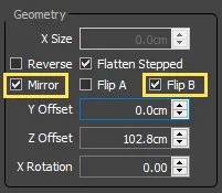
From the Properties panel, turn on Mirror and check Flip B
-
Enter a value of 42.6 for the Y Offset parameter. You will now two rows of lights, one either side of the central spline.
-
However, there is a problem, the connection brackets are not aligned correctly as each row is calculated independently. The connectors should be aligned perpendicular across the spline.
-
To fix this, go to the Rules tab and turn on Sync Offset
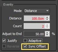
The evenly positions for both rows are now calculated based on the central spline and the Segments are translated into the correct position perpendicular to the path.
-
To finish up this section, change the path for the lights and rc_walls to curved_spline. The walls and lights are now complete.
Exercise: Exploring Default Segment Tiling
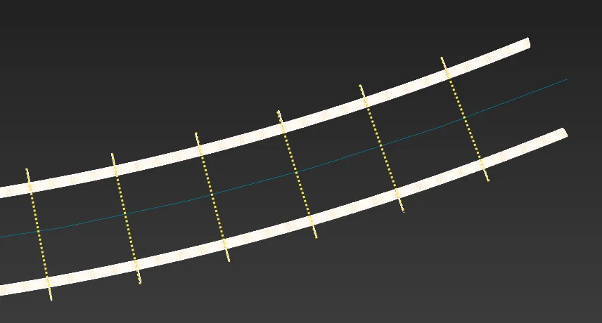
The remaining area, in between the Start, End, Corner and Evenly parts of the array, is filled with Default segments. Exactly how these are distributed is defined by the settings found in the Default Mode group.
There are 4 modes, each of which determines how the object is repeated and scaled to fill the available space. In this exercise we'll use these settings on the remaining parts of the corridor to illustrate how these settings can be used.
Tile (Default)
In the tile mode, default segments are repeated along the path. When a segment is interrupted by an Evenly, Corner or End part of the array, is simply sliced to ensure a perfect fit. In our corridor style we will use this technique on the vertical pipes attached to the walls.
-
Select rc_wall_pipes and apply it to the straight_spline path.
-
Open the Style Editor and ensure the Default node is set to Tile.
-
Scrub the timeline, as the spline changes length and the segments pass the end of the path you will see they are sliced.
-
Change the path to curved_spline to add this style to the final corridor.
Scale
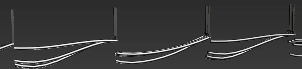
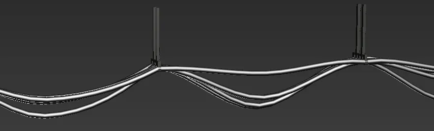
Instead of tiling multiple segments you can use Scale node to add a single segment and then scale it to fill the space between the initial and final positions of the path section. Remember, a section is defined as the distance between Start, End, Evenly or Corner parts of the array and in this exercise we'll use scale mode to add the wires and pipes between Evenly spaced support brackets.
-
Select rc_wires and apply it to the flat_spline path. You'll see that in the Default tile mode the cables are sliced incorrectly
-
Open the style editor and change the Default Mode to Scale. The single cable segment is now stretched between the supports and the style is correct. Even if you change the "evenly" Distance, the cables re-scale to match.
-
Change the path to curved_spline to add this style to the final corridor.
-
Repeat this process for rc_ceiling_pipes.
Adaptive
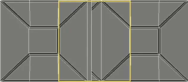
Adaptive mode is a hybrid between Scale and Tile. It calculates the number of whole segments that would fit into a path section and then scales them all equally on the X axis to fill the available space. This mode generates complete segments, with no clipping at the start or end of a spline segment. We can use adaptive mode on our floor tiles to makes sure that the pattern is not disrupted by incorrectly sliced geometry.
When Adaptive mode is active, Corner > Bevel settings are unavailable. In the next section we will look at a workaround for this limitation.
-
Select rc_floor and apply it to the
_flat_splinepath.You'll see that in the default tile mode the floor tiles are sliced incorrectly and the patterns do not quite line up.
-
Open the style editor and change the Default node to Adaptive. Only whole tiles are now used, and they are equally scaled to fill the available space. Even if you change the "evenly" Distance or spline length, new segments are added and scaled to ensure a perfect fit.
-
Change the path to curved_spline to add this style to the final corridor.
In Adaptive mode the Adaptive Percentage value specifies the minimum length of remaining space (expressed as a percentage of the segment's original size on the X axis), at which a new segment will be added. For example if a segment's X-dimension is 1m and the path section length is 4.25m, the segment will fit into the distance 4 times (4 x 1m = 4m). The remaining space is 0.25m, therefore a new segment will be added if the Adaptive Percentage is set at or below 25%.
Count Mode.
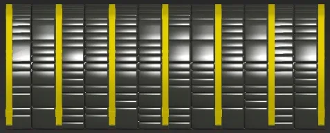
Count mode scales a fixed number of segments to fit between the start and end positions of a path's section. In this example we will use this mode to ensure there are always 3 ducting boxes between the supports.
-
Select rc*ducting and apply it to the
_flat_splinepath. -
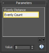
Open the Style Editor and change the Default node to Count. you can now change the number of segments to scale on a path section using the Count value directly inside the Style Editor, or by exporting the value and connecting it to a numeric node so that it can be easily accessed from the modify panel. Set this value to 3, and you will always get 3 ducting boxes between the supports even if you change the length of the spline or evenly distance.

-
Finally, to complete this exercise change the path to curved_spline to add this style to the final corridor.
-
Press C on the keyboard to change to the camera view and see the inside of the finished sci-fi corridor.
Because Adaptive, scale and count mode prevent RailClone from slicing geometry it has the potential to improve the number of segments that remain instanced. Any sliced segment contributes to the overall polygon count whereas scaled segments do not. Of course this does not apply if the segment have also been deformed to follow the spline in which case they will also contribute to the overall poly-count.
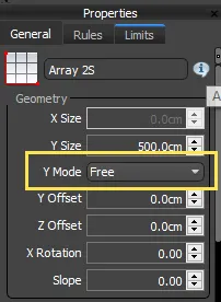
Y Mode
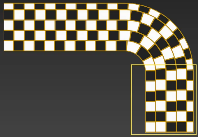
To round up this chapter we'll take a look at one last mode that can affect the distribution of Default segments. The A2S generator has a little known Free Alignment Mode that allows you to calculate the spacing of default segments for each row independently. To see how this is useful we'll look at typical paving style.
-
Open
chapter_7_free_mode.maxfrom the downloads for this guide.You'll find a simplified paving style with alternating black and white tiles to accentuate the behaviour of the default segments.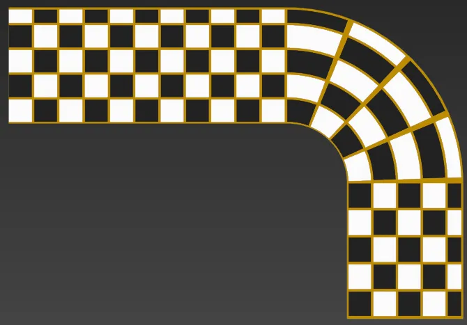
Notice that on the corners the tiles get larger the further out from the corner they are. This is because the style is using the default Aligned node in which segments are scaled so that the same number of them appears in each row. 2. To fix this we can force each row to calculate its own default spacing. Just open the Style Editor, select the Generator and change the Y Mode to Free from the properties panel.
-
This fixes the corner, but you can see that we've lost the checker pattern after the bend:
-
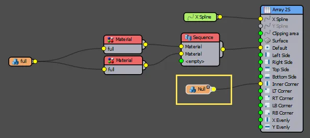
To return the pattern we need to break the array into different path sections, one before the bend, the bend itself, and then one afterward. At the moment because there are no Evenly of Corner segments the entire spline is considered to be one section. Fortunately the solution is very simple. Just wire an empty Segment operator to the Corner input to break the path at that point.
-
Each row in the corner is now calculated separately but the pattern is reset on the straight sections!

In this section we've looked at all the setting found in RailClone that influence the distribution of automatically repeating segments. Other segments are placed according to the start, end and vertices of the base spline or the size of the array. In the next chapter we'll take a deeper look at some of these as we explore how to master the controls for corners.
Related Tutorials

The five-part stadium tutorial is a great introduction RailClone that features many tips to help you get the most of the spacing modes.
Learn how to use scaling mode to create power lines. This tutorial is similar to the cables style found in the sci-fi corridor
For more information please see the 1D arrays - Generator L1S and 2D arrays - Generator A2S sections of the online documentation.