Tips for Creating "Parts" with RailClone
RailClone's approach to creating parametric objects is unique. By instancing, sequencing and combining modular, repeatable components of geometry; objects featuring huge poly-counts that render with no performance overheads and rapid iteration are easy to create.
If you've been using RailClone for a while, you'll doubtless have experimented with the built-in library styles; however, one of the most important steps in moving from using RailClone's built in library styles to creating and using your own, is understanding how to create modular geometry that works well with RailClone's two array types. This subject has already been touched on briefly In the Getting Started with RailClone Guide where we outlined a few rules for creating geometry for L1S and A2S generators. In this chapter we'll recap and expand upon that foundation and look at 11 useful guidelines that can help make creating geometry for RailClone even easier.
Rule 1 - Model for the generator you intend to use
The most important thing to consider when creating source geometry "parts" to be used by RailClone is the type of generator you intend to use. To do this you'll need to examine the design you intend to create, and analyse how it will fit into one of the two array types. To do this it's obviously important to have a good understanding of RailClone's rule-based work flow, so if you need a recap we recommend you check out Key Concepts: Array Based Instancing from the Getting Started with RailClone Guide .
Once you've ascertained the most suitable array, you'll have a list of the possible inputs that can be used. For example, if you're planning to use an L1S generator you have 5 possible inputs, while the A2S generator has over twice as many with 12 possible inputs. These are combined in the arrays in rows and columns as shown in the table below. Remember the default rows and columns are repeated or scaled in between the other segments to fill in the array.
| L1S Array | Start | Default | Evenly | Corner | End |
|---|---|---|---|---|---|
| A2S Top Row | Top Left Corner | Top | X-Evenly/Top | Corner/Top | Top Right Corner |
| A2S Y Evenly Row | Left /Y-Evenly | Y-Evenly | X - Evenly | Corner | Right/Y-Evenly |
| A2S Default Row | Left | Default | Right | ||
| A2S Bottom Row | Bottom Left Corner | Bottom | X Evenly/Bottom | Corner/Bottom | Bottom Right Corner |
Though there is a wealth of inputs to help you create your designs, there are also a few limitations that you should be aware of. For example, in the A2S array, there isn't an input to target the ends of a Y evenly Row or an X Evenly column; there's also no input for the intersection between the Y evenly row. and X Evenly columns either. Of course, it's possible to get around this limitation using conditional statements and other tricks, but it's still an important consideration to bear in mind when you start to create your assets.
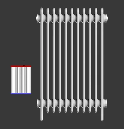
In many cases you will have the choice of either of the two generators to create a style, when this is the case, the decision of which array to use can be determined by questioning how many dimensions you need to adjust in the style. For example, let's imagine you have a job that specifies a particular style of radiator as seen in the screen grab shown below.
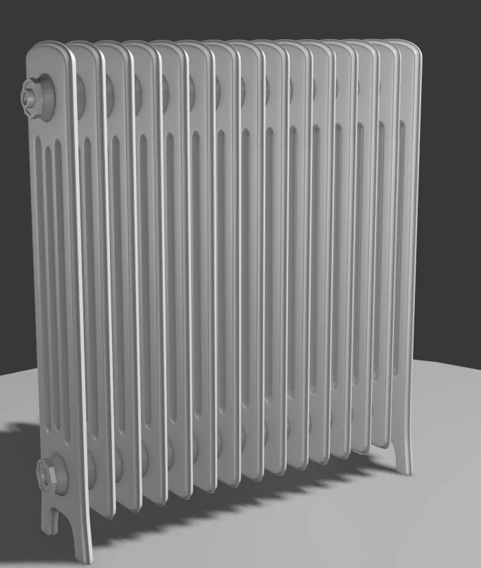
If all the radiators in the project have the same height but different lengths you can use the simpler L1S - linear generator. This is generally much easier to create source geometry for. In this case you can re-create the style with only two segments. The image below shows how you would analyse this design.
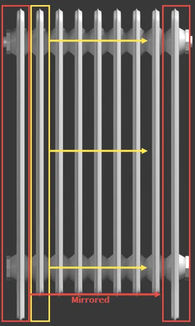
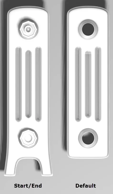
As you can see there's a repeating radiator fin section that is marked in yellow. In an L1S array the segment wired to the Default input is repeated to fill in between Start, End, Corner and Evenly segments, so we can model the area marked as yellow to create our Default segment's geometry. This will be adaptively tiled between a Start and End segment that incorporates the radiator's legs and valves, marked in red. There's no need to model this twice to create separate models for the Start and End, as we can simply use a Mirror operator to flip and reuse a single segment. Based on this analysis we only need the following two segments to create a radiator of any length.
However, if the radiators are of different lengths and leights you can use an A2S generator to create an adjustable two-dimensional array. To use this generator the geometry will need to be prepared quite differently and when we analyse the design, this time we need to consider how to break up the radiator to fit into rows and columns.
Firstly let's look at the columns, the same principle applies as we used to analyse the design for the L1S array. There's a Start column, mirrored to create the end, and then repeating fins in-between. But that's not all, we also need to consider the Y axis. The top and bottom have distinctive geometry which cannot be mirrored, so we'll also need separate segments in each column for the top and bottom of the array. We'll also need a default row which tiles in between the top and bottom rows as the height is adjusted. The image below illustrates how to approach analysing this radiator design to create models for the A2S array.
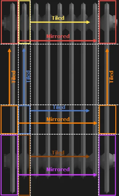
This pattern is derived from thinking about the model as a series of horizontal and vertical slices that create columns and rows. By slicing the model as shown by the white dashed lines we get the following segments, organised by row:
Top Row
The Top Left Corner and Top Right Corner segments are shown in red. Only one segment is needed because we can use a mirror operator to create the other side.
The Top segment is shown in yellow, this will be tiled on the X axis to fill in between the Top Left Corner and the Top Right Corner.
Default Row
The Left and Right segment are shown in Orange, Only one segment is required as we can mirror it to create the other side. This segment will tile on the Y axis to fill in between the Top and Bottom rows.
The Default segment is shown in blue. This tiles on the X axis to fill in between the Left and Right segments, and on the Y axis to fill in between the Top and Bottom rows.
Bottom Row
The Bottom Left Corner and Bottom Right Corner segments are shown in magenta. Like the top corners, only one segment is needed because we can use a mirror operator to create the other side.
The Bottom segment is shown in brown, this will be tiled on the X axis to fill in between the Bottom Left Corner and the Bottom Right Corner.
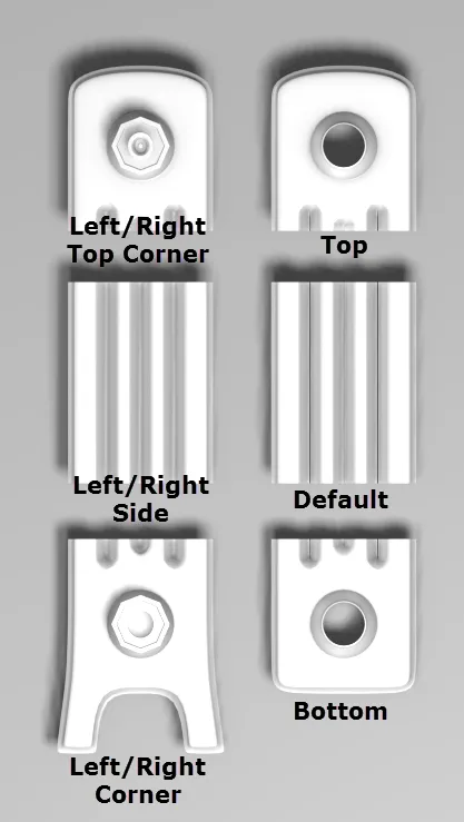
Based on this analysis we can model the following six segments to create a radiator of any length and height. To see the
finished file, open chapter_2_radiator.max from the
downloads for this guide.
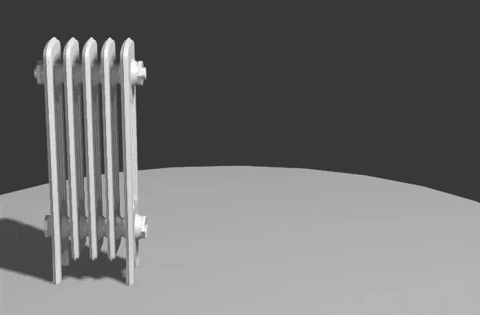
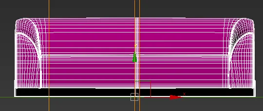
If you are creating a 2D array with no gaps, then It's important to ensure that the height of all the segments in a single row is the same. The height of a row is determined by the bounding box of the largest segment and rows cannot automatically overlap. In the example below you can see what happens to the radiator style if we adjust the height of the Side segment so that it does not match the Default segment.
As you can see from these examples, the key to creating usable assets for RailClone is dependent on a good understanding of the inputs of the two types of generator. If you'd like to look at some examples, please feel free to reverse engineer our built-in library objects. The geometry for each of the segments can be extracted into the scene to be studied or edited by selecting the node and clicking
from the toolbar in the Style Editor.
Rule 2 - Consider the default mode you are using. Scaled, Tiled, or Adaptive?
When you are creating geometry to be used in the Default. Bottom, Top or Y Evenly inputs, it's helpful to keep in mind the Default Segment Mode you intend to use. This set of options, which can be found in the generator's Properties > Rules Panel, determine the way in which segments are distributed along a path section. In the default Tile mode, the segment is simply replicated along the path. If the last segment in the section is too long, it is sliced to fit the path's length. This is the most forgiving of the Default modes, and more or less any geometry will be fine as long as you don't mind it being sliced at the end of the path.
Instead of tiling you can also use Scale node to stretch a single segment to fit the path section. Because they are stretched, segments for use with Scale node will generally require a consistent cross-section to avoid unwanted distortion. This mode is well suited for situations where you might normally be tempted to use the Sweep modifier. To create a cross-section for this mode, the easiest way is often to draw the cross-sections in the Left or Right viewport with spline tools, and then add an extrude modifier to create polygonal geometry.
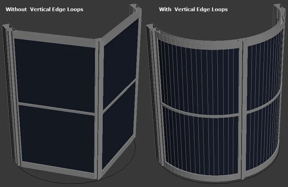
Another important consideration when creating geometry for Scale mode is whether of not you would like the geometry to follow the curves of the path or travel in a straight line from the start of the path section to the end. If you don't include any vertical edge loops, the geometry will scale in a straight line, however including vertical cuts will allow the segment to deform to follow the path.
Count node allows you to specify an exact number of whole segments to use between the path start and end. Depending on the number specified this can also cause stretching along the X axis so be sure to only use geometry where that is expected and acceptable.
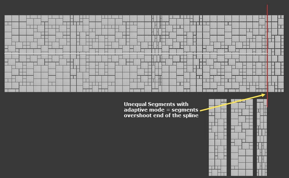
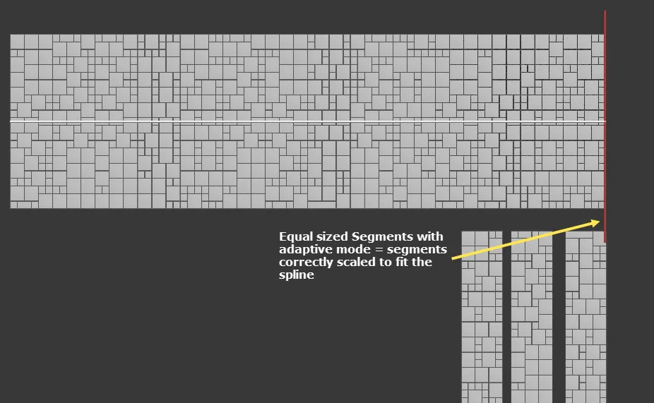
Finally, Adaptive node is similar to Tile except instead of slicing the final segment, this mode calculates the number of whole segments that would fit along a spline segment then subtly scales them on the X axis to ensure they fill the available space. Any distortion on the X axis is generally quite small, so you can get away with modelling as you would when using Tile. There are very few restrictions when modelling for Adaptive mode unless you are planning to use multiple default segments on a single path section, for example by using the Compose, Sequence or Randomise operators. If you do use default segments with different lengths, you could find that the final segment sometimes overshoots the ends of the path. The Adaptive algorithm is only able to accurately scale the meshes if they are identically sized on the X axis, so if you plan on using this mode with multiple segments, ensure they are all the same size.
We will look at tiling modes in more detail in Chapter 7 - Master Spacing Modes of this guide.
Rule 3 - Only Model the smallest repeatable components
To use RailClone efficiently, you should try to identify the smallest repeatable modules of geometry, and create only them. There's no point in spending valuable time modelling geometry that is easier to generate automatically using RailClone. By carefully examining your designs, as in the radiator example above, you can identify the minimum number of components required to create the style. However, as we've also seen, the critical consideration is that the parts should fit into one of RailClone's 2 array types. In some situations, you may be able to identify repetition in a design that does not easily fit into a L1S or A2S generator. For example, take a look at this ledge wall example:
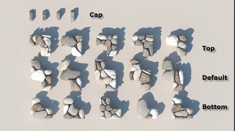
We can identify 5 small repeated components, shown highlighted below.
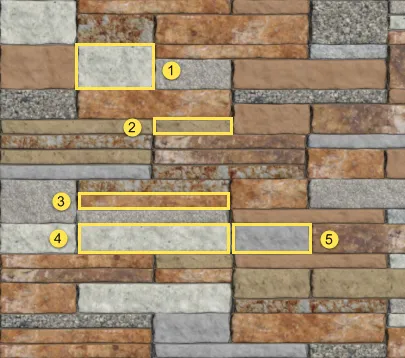
However, because there are 3 different height of the stones they won't fit into an A2S array without creating gaps, (Remember the A2S array requires all the segments in the array to be an equal height). Although these are the smallest elements, we'll need to think a little more about the style to make it work with RailClone. To fix this, Instead of using individual stones, we can create combinations of stones until they are all the same height, and then add these to RailClone. With these 5 stones there are a number of possible variations as show below.
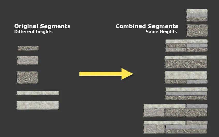
These aren't the smallest components in the wall design, but they are the smallest that will fit easily into the A2S array.
So, despite the heading title, smaller isn't always better. There's a balance to be found between the polygon count of the source geometry and the number of segments that are created in normal use. Another consideration is if a segment has a very high poly-count and is likely to be sliced or deformed. In this case it will no longer be instanced and contributes to the total amount of static geometry in the scene. Therefore, if you know that many of the segments are going to be sliced or deformed you should try to keep the polygon count of each individual segment relatively low. This trade-off between the number of instances and the polygon count of segments that will be sliced or deformed is the key to producing well optimised styles. There's no fixed figures for this, it depends very much on your scene and chosen renderer. We recommend you do some tests if the style is likely to produce many millions of instances.
Rule 4 - Re-use segments using Rotate and Mirror
This is very closely related to the previous points. As well as looking for elements in the design that are repeated, try to look for geometry that can be re-used by rotating or mirroring on the X, Y, or Z axis. RailClone includes the ability to transform or flip geometry making it even easier to reuse.
For example, take a look at this bench design byBMW Group Designworks USA.

This can be created in RailClone using only 2 segments. The metal ends of the seats are unique and cannot be broken down any further, whereas the wooden seat itself is a simple profile that can be scaled along the length of the bench. Because the end can be mirrored there's no need to create a segment for each end - just use the mirror operator. The two segments to recreate this style would look like this:
See the chapter_2_bench.max from download file for an
example of this finished scene
In the radiator example above we also used the same technique, by modelling the segments for the left hand side of the radiator and mirroring them, we were able to create the segments for the right.
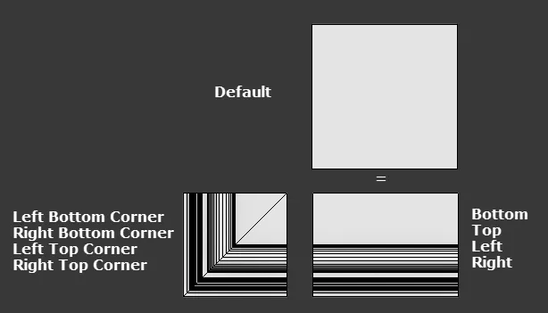
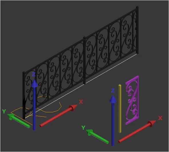
When you're using the A2S array you have even more opportunities to re-use geometry. For example, let's look at the geometry required to make a simple picture frame with an adjustable height and width. If we slice up the model we can see that there are 9 segments required to make this style work.

9 pieces is a lot for such a simple style, fortunately it can be created with far fewer. In the diagram above there are 4 separate corners segments, but by mirroring the bottom left corner segment on the X axis we get the bottom right, mirror on the Y axis to get the top left, and finally mirror the segment on the X and Y axis to get the top right. In this way the same segment is used 4 times to fill the corners with the array. The same is true of the bottom of the frame which can be mirrored on the Y axis to create the top and rotated by 90 degrees to create the sides. By reusing segments with mirror and rotate we're able to reduce the number of source objects from 9, to 3.
To see this style, chapter_2_picture_frame.max from
download
Rule 5 - Mirror geometry to the other side of the spline
In the previous example we looked at how you can save modelling time by mirroring or rotating segments so that they can
be re-used. In addition to the ability to use the Mirror operator to flip individual elements, the L1S generator also
features the ability to duplicate and mirror the output of an entire generator either side of the spline. Take for
example the Median style from the built-in library:
This simple style uses 2 segments, a Default and an End, but as you can see, we've only modelled one half of the median:
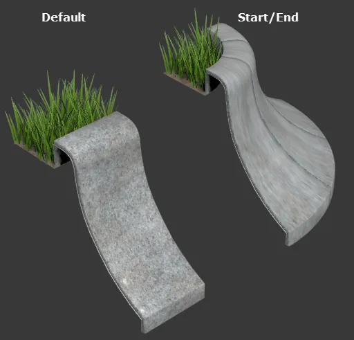
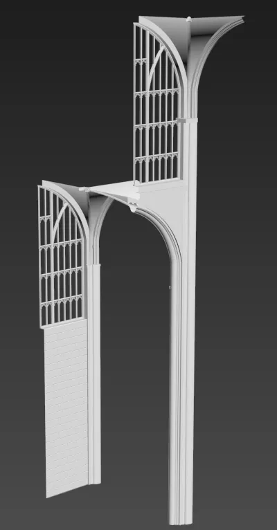
By exploiting symmetry in this way you are able to reduce the amount of modelling necessary to create the style. Let's look at another example that uses an L1S Generator with Symmetry and a Mirror operator to make the amount of modelling necessary to create the style minimal.
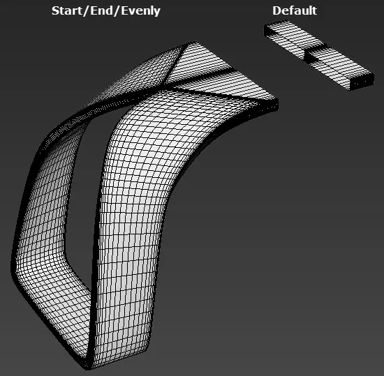
In this second example, imagine we're blocking out a Gothic style interior. We can create a segment like the image below - it looks like a fragment but by using the mirror operator, a sequence operator and turning on Symmetry for the generator we can create an entire interior.

Exercise: Using Mirroring Tools
-
Open chapter_2_symmetry.max.
-
Select the
rc_cathedralRailClone object. -
Open the Style Editor the Cathedral segment has already been added to the style.
-
Select the segment, go to the Properties Panel and change Y Alignment to Bottom
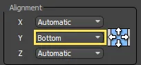
This will move the segment so that it's aligned to one side of the spline instead of its centralised.
-
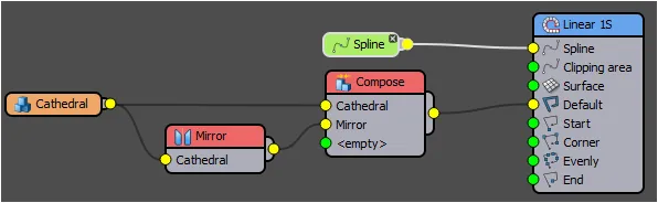
Create a new Compose operator. We'll use this to alternate between the normal and a mirrored version of the segment along the X axis.
-
Wire the Segment to the Compose operator's first input.
-
Create a new Mirror operator and wire this to the Compose operator's second input.
-
Wire the Segment to the Mirror operator's input. You're node tree should now look like this:
-
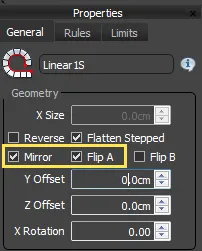
You'll now have half a Cathedral, to create the other half select the Generator open the Properties and turn on Mirror in the Geometry group. The geometry is copied to the other side of the spline, but it hasn't been flipped. To do this turn on Flip A to complete the style.
In this example we maximised the reuse of the segment by mirroring it on two axes. The great thing about working with so little geometry is that making design changes is very fast. At the moment this Cathedral is pretty simple, but if we wanted to start modelling additional detail, re-texturing, or adjusting the proportions, we only need to change the one segment and all the changes will cascade through the entire style.
Rule 6 - Combine segments to create new geometry. Use Compose and Sequence operators to combine geometry and create patterns
Save time modelling geometry by finding opportunities to combine segments. RailClone includes a Compose operator that enables you to add two or more segments together to create a new component. Combined with the Sequence and Reverse operators you can create new geometry by combining smaller units of geometry found elsewhere in the design.
Consider this railing for example:
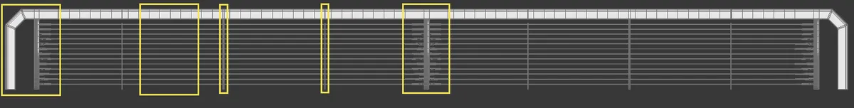
This style has a start and end, then a pattern of thin, medium and thick posts. The starts and ends also have connectors for the metal cables. You could break this design down into these 5 sections:
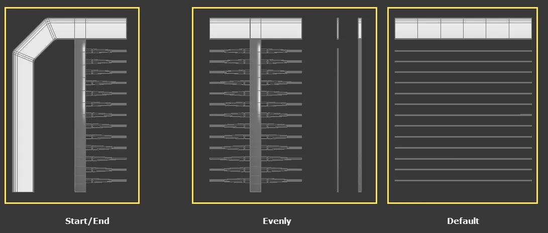
But actually if we look at the design a little more closely you'll see that even within those segments there's quite a lot of repetition.The cable connectors and the large posts are repeated in one of the evenly segments and also the Start and End segments. So we can break this down even further, like this:
This version allows you to re-use the cable connectors and the large post for both the Evenly and the Start and End segments. It may seem counter-intuitive that in this version we now have an additional segment but if you have to edit the style, for example the cable connectors, you'll only need to do it once. In the previous version you would need to edit the cable connectors on the Start and End segment and both sides of the large Evenly post to make a change. Editing in multiple locations like this can have a negative impact on a fast, iterative work flow, which is why it is beneficial to break these models down as much as possible. To understand how to do this it helps to see how RailClone is used to reconstruct a style like this, so in the following exercise we combine these 6 segments using Compose, Reverse and Sequence operators to create the railing style.
Exercise: Combining segments using compose and reverse operators
-
Open
chapter_2_compose.maxfrom the downloads for this guide -
Select
rc_bridge_railingand open the Style Editor. The segments have already been added to this style. -
First we'll create the Start and End. Create a new Compose operator and wire the segment called
railing_endto the First input. Next we want a post so connectrailing_postto the second input. Finally, we need the cable connectors, wirerailing_connectorto the third input. These 3 segments are now combined to create the start segment. Wire the Compose operator to the Generator's Start input. -
To reuse the Compose operator for the End input you use a Reverse operator. This will invert the order of the 3 segments and also give you the option to mirror the geometry on the X axis. To use it, create a new Reverse operator and connect the Compose node to its input. Next wire the Reverse operator to the Generator's End input.
-
Select the Reverse operator and turn on Mirror Segments on X.
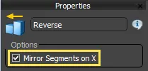
-
Next we'll create the large post with the cable connectors on either side. To do this create a new Compose operator and wire a Mirror operator to the first input. Wire
railing_connectorto the Mirror operator, and wire railing_post to the Compose operator's second input. Finally wirerailing_connectorwithout the mirror to the third input. This creates a large post with cable connectors on both sides. 7. As well as the large post, there are 2 other Evenly segments in this style: A thin and a medium post. Examining the finished design above you can see these are used in repeating pattern of thin post - medium post - thin post - large post. To achieve this, create a new Sequence operator. Wire the segments to the sequence operator in the correct order and connect the Sequence operator to the Generator's Evenly input. -
To complete the style, wire the
railing_defaultsegment to the Generator's Default input. The finished node tree is shown in the image below, notice how therailing_postandrailing_connectorsegments are re-used in the Start. End and Evenly inputs.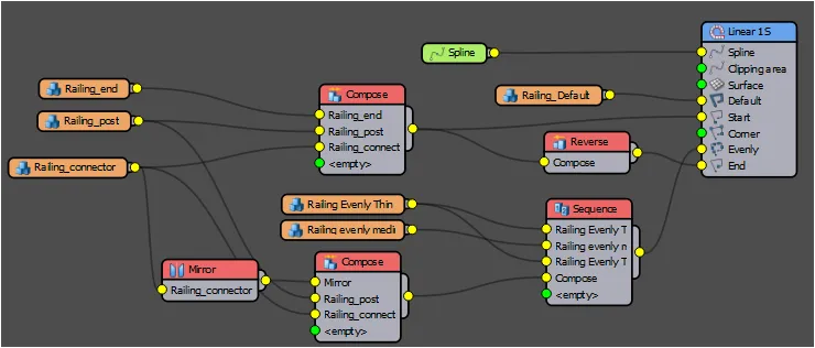
Understanding how the compose operator combines segments to build new components can help you to build smaller and more efficient modular geometry.
Rule 7 - Building components Individually vs using the Slice modifier?
Everyone has their own approach to modelling, and it would be remiss of us to suggest the tools you should use to create geometry for RailClone. That said, there are broadly two possible methods you can use for modelling modular segments. You could either model each component individually, or model the full design as a single object and slice it into smaller parts.
Each has its advantages and disadvantages and your choice of which to use is often determined by the project at hand. If the object you are trying to create is already clearly divided in real-life into distinct pieces it is often easier to model it this way. Things like floors, ceilings, façade systems etc. are often made up of components like this, and this is often the best approach to model them for RailClone.
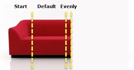
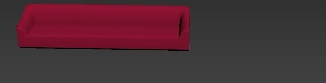
On the other hand, if the model has elements that start in one segment and continue seamlessly to an adjacent segment, or if you've purchased or been provided with an existing model you'd like to parametrise, you'll probably find it easier to divide it into parts using a number of slice modifiers. For example, let's say that you wanted to parametrise this sofa from Design Connected .

Firstly we need to think about how this will fit into a RailClone generator. In this case we only want to change the length so an L1S generator is most appropriate, and we can split the sofa into these sections.
To do that you'd use 3 slice modifiers. Try the following exercise to see how they are placed.
Exercise. Slicing an object
-
Download the sample model from Design Connected
-
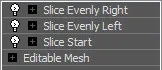
Apply a Slice modifier and rotate the slice plane by 90 degrees. Move the slice plane on the X-Axis so that it is just to the right of the sofa's arm. Rename this slice modifier Slice Start
-
Right-click on the slice modifier and select Copy. Right-click again and click Paste. You now have a second slice modifier that can be moved to the left-hand side of the seam in the middle of the sofa. Rename this modifier Slice Evenly Left .
-
Copy and Paste Slice Evenly Left to create a third slice modifier and move its slice plane just to the right of the seam in the middle of the sofa. Rename this modifier Slice Evenly Right. You'll now have 3 slice modifiers that we can use to create the segments for an L1S array.
-
Select Slice Start and change the Slice Type to Remove Top. This will leave you only the arm of the chair. Rename the object Sofa Start
-
Duplicate the model by pressing CTRL + V. Change the Slice Start Slice Type to Remove Bottom. Select Slice Evenly Left and change the Slice Type to Remove Top. This will create the default segment. Rename the object Sofa Default.
-
Duplicate the model a third time by pressing CTRL + V. Change the Slice Evenly Left modifier's Slice Type to Remove Bottom. Select Slice Evenly Right and change the Slice Type to Remove Top. This will create the "evenly" segment. Rename the object Sofa Evenly.
To create the RailClone style for these segments, follow these steps:
-
Create a new Style with a single L1S Generator and a Spline input.
-
Create a new Segment node and pick Sofa Start as the source object. Change the segment's Properties > Alignment > Y to Pivot. Because all the objects were originally created from the original sofa, their pivots should line up perfectly.
-
Wire the new segment to the generator's Start input.
-
Create a new Mirror operator and wire the segment to its input. Wire the Mirror operator to the Generator's End input.
-
Create a new Segment, set the Y Alignment to Pivot and use Sofa Default as the source geometry.
-
Select the Generator and set Properties > Rules > Default > Mode to Scale.
-
Create a new Segment, set Y Alignment to Pivot and use Sofa_Evenly as the source geometry.
-
Wire the new segment to the Generator's Evenly input. You will now have a parametrised version of the sofa created by dividing the source geometry into segments using the Slice modifier.
 Use RailClone Slice
To speed up the slicing process RailClone includes RailClone Slicer, a modifier that can control slice planes and create segments that are ready to be used in RailClone's 1D or 2D Arrays. You can learn more about the plugin here
Rule 8 - Pivot orientation
One of the problems new users often encounter is aligning segments correctly within the array. Often a segment is added only to find it is rotated incorrectly. The temptation at this point is to use the Segment's Fixed Transform settings to correct the rotation, but a lot of time and confusion can be saved by ensuring the pivots on the source geometry are oriented correctly. The L1S and A2S array both orientate the source geometry in the same way, but some confusion can arise when an A2S array is rotated to create a vertical style like a wall, window or facade. The 3 examples below should make clearer how RailClone uses aligns segments in the two array types.
Segment alignment in L1S Arrays
The local X-axis of the source object is aligned to follow the spline. If no spline is used, the object is aligned to the RailClone object's local X-axis.
The local Z-axis of the source object is aligned to the RailClone object's local Z axis.
Segment alignment in A2S Arrays
The local X-axis of the source object is aligned to follow the spline. If no spline is used, the object is aligned to the RailClone object's local X-axis.
The local Y-axis of the source object is aligned to follow the spline. If no spline is used, the object is aligned to the RailClone object's local Y-axis.
The local Z-axis of the source object is aligned to the RailClone object's local Z axis.
Segment alignment in Rotated A2S Arrays
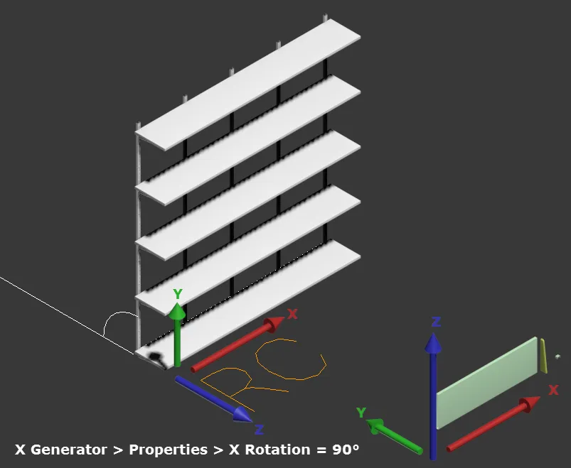
Some confusion can arise when an A2S array is rotated using the Generator's X Rotation feature. In this case, the array is built as usual on the XY plane and then rotated around the X-axis. In this case, the final orientation of the source geometry and their final orientation in the array does not seem to match.
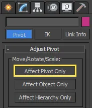
In order for geometry to be correctly aligned in the array, it may be necessary to adjust the orientation of the local axis. To do this:
-
Select the Geometry object.
-
Go to 3ds Max's Hierarchy Panel.
-
Click Affect Pivot Only.
-
Rotate the Gizmo to the correct orientation.
Rule 9 - Pivot placement
When you add a segment to RailClone, it is positioned in relation to the base spline and adjacent segments using the extents of its own bounding box. In order to accurately build a style it is helpful to understand how this works, because the alignment varies depending on where the segment appears in the array.
Unless you specify otherwise, segments use an Automatic node that changes the pivot used for placement according to whereabouts in the array the segment is used. For example, a segment used in the Start input of an L1S array will be aligned so that the left-hand side of the bounding box is aligned with the first vertex in the array. The exact same segment if used in the End input will use the opposite side - the right of the bounding box. And if you use it in the Evenly input, it will use the centre of the bounding box.
Though this seems confusing it is in fact quite logical when you consider why these changes are taking place. For the start segment to use anything but the Left of the bounding box as a pivot would result in a mismatch between the length of the path and the length of the geometry.
In the table below you can see the alignment used when a segment is in Automatic mode wired to the different inputs of an L1S array. With an L1S array, the Y and Z alignment remain constant, only the X alignment changes.
| Start | Default | X-Evenly | Corner | End |
|---|---|---|---|---|
X: Left | Y: Centre | Z: Bottom | X: Left | Y: Centre | Z: Bottom | X: Centre | Y: Centre | Z: Bottom | X: Centre | Y: Centre | Z: Bottom | X:Right | Y: Centre | Z: Bottom |
This is different in an A2S array where only the Z alignment is constant, The X alignment is the same as the L1S array and the Y alignment now varies depending on which Row a segment is used in.
| Left/Start | Default | X-Evenly | Corner | Right/End | |
|---|---|---|---|---|---|
| Top | X: Left | Y:Top | Z: Bottom | X: Left | Y:Top | Z: Bottom | X: Centre | Y:Top | Z: Bottom | X: Centre | Y:Top | Z: Bottom | X:Right | Y:Top | Z: Bottom |
| Y - Evenly | X: Left | Y: Centre | Z: Bottom | X: Left | Y: Centre | Z: Bottom | X: Centre | Y: Centre | Z: Bottom | X: Centre | Y: Centre | Z: Bottom | X:Right | Y: Centre | Z: Bottom |
| Default | X: Left | Y: Bottom | Z: Bottom | X: Left | Y: Bottom | Z: Bottom | X: Centre | Y: Bottom | Z: Bottom | X: Centre | Y: Bottom | Z: Bottom | X:Right | Y: Bottom | Z: Bottom |
| Bottom | X: Left | Y: Bottom | Z: Bottom | X: Left | Y: Bottom | Z: Bottom | X: Centre | Y: Bottom | Z: Bottom | X: Centre | Y: Bottom | Z: Bottom | X:Right | Y: Bottom | Z: Bottom |
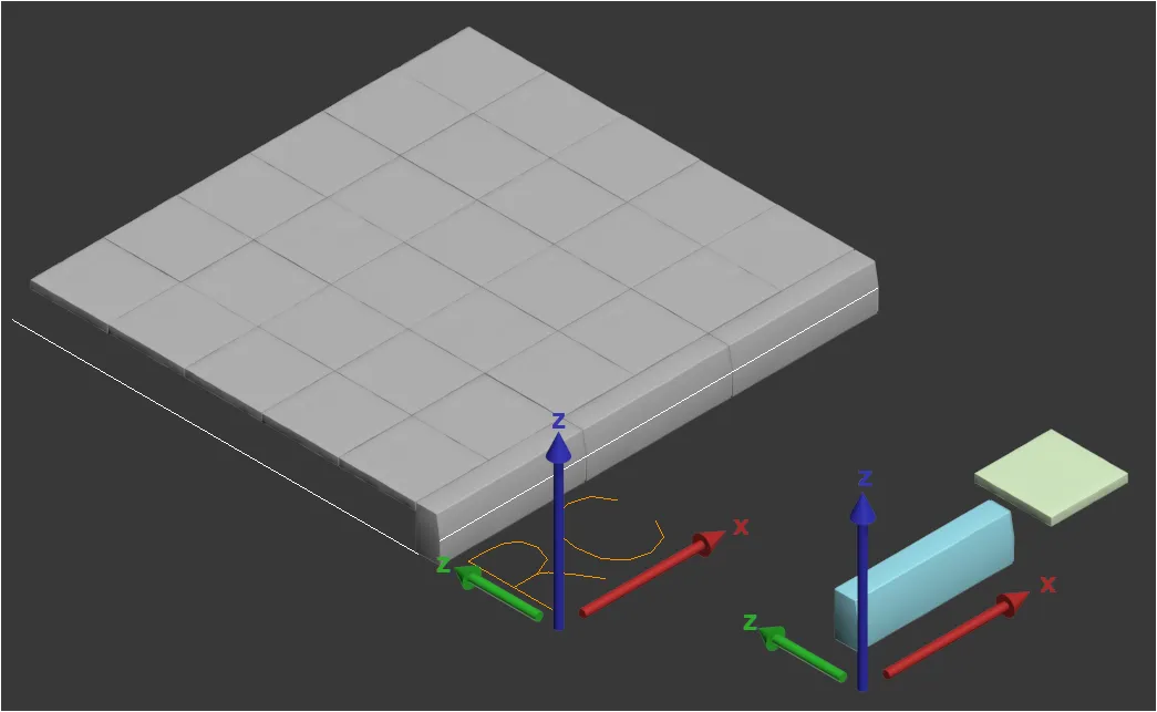
The images below give you a visual representation of these alignment changes in action. As you can see they are necessary to ensure that the geometry fits within the limits of the size of the array.
X Alignment
 L1S and A2S
Y Alignment
 L1S
L1S
 A2S
A2S
Z Alignment
 L1S and A2S
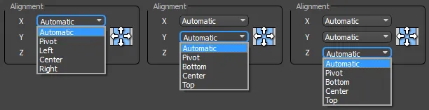
In most cases, Automatic alignment works well, but in some scenarios, you may want to manually specify how the segment is aligned. For each axis you RailClone offers a number of different options as shown in the below.
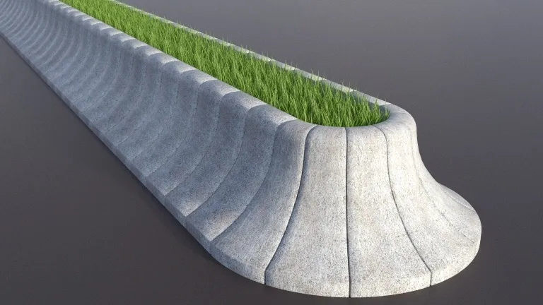
For example, a simple Pylon style with a segment for cables and another for the towers will not work well with default pivot alignments. The side view below shows these segments:
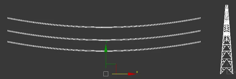
The automatic alignment would move the cables down to the ground so that the bottom of their bounding box is on the spline. We could of course move it back into position in RailClone using the Segment's fixed transform values, but by setting the pivot correctly on the source geometry and changing the Segment's Properties > Alignment > Z value from Automatic to Pivot the problem is solved much more easily.
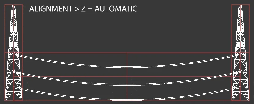
To see this style, download chapter_2_pylons.max
Rule 10 - Disguise joints with interlocking geometry
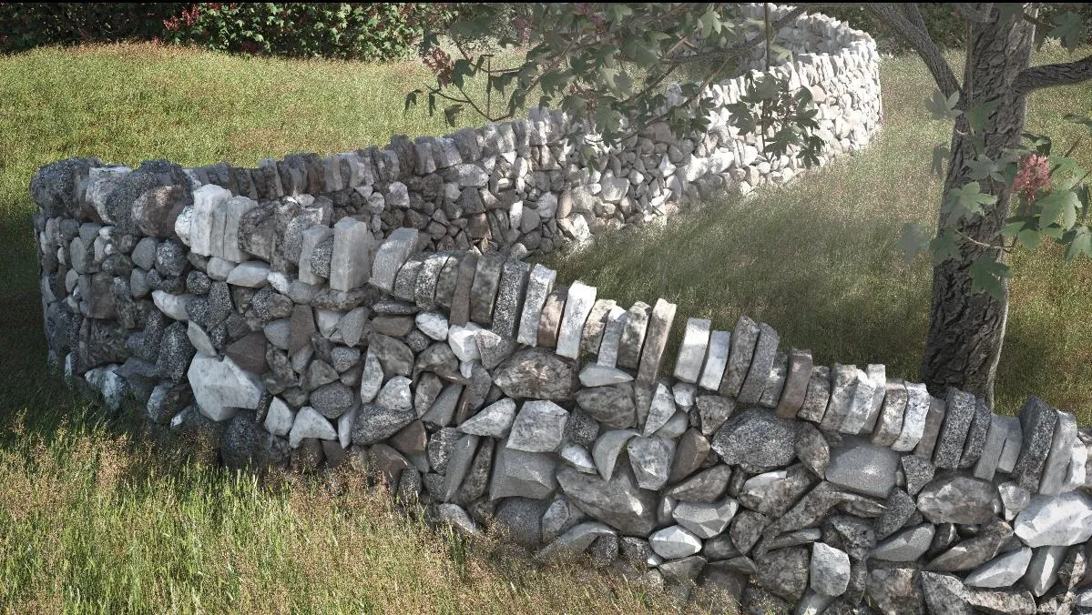
RailClone is grid-based which can occasionally be a problem when you want to create the illusion of a randomised pattern. To get around this you can create an illusion of chaos by creating overlapping segments of the same size and shape but that contain randomly shaped elements. For example, in this example of how to approach a dry stone wall you can see tetris-like individual segments that are consistent in "size" and "shape", however within each one there is no clear order.
When these lock together the grid of the underlying array becomes much harder to detect.
Rule 11 - Reset XForms
Generally speaking, it's a bad idea to scale geometry at object level, but if it is unavoidable, or you've rotated the object, and you want a quick way to reset the pivots to world space, then use the Reset XForm tool found in Max's utilities menu. If you don't then these changes will not be reflected when the segment is imported into RailClone.
To reset the XForm:
- Select an object.
- Go to the Utilities panel and click Reset XForm.
- From the Reset Transform rollout, click Reset Selected.
As well as resetting scale values, the Reset Xform utility realigns the pivot to world space, so you'll want to make sure that the object is orientated correctly before using it.
The XForm modifier can also have another useful purpose. If you want to animate the transforms of the source geometry, you can apply a XForm modifier to the object, select the Gizmo sub-object and animate the rotation. translation or scale. Unlike animating the object directly, keyframing the Gizmo allows the animation to be maintained when the geometry is added to RailClone.
Rule 12 -Correctly assign material IDs to "parts"
When creating custom geometry for RailClone, it's important to
take into consideration the management of the object's material IDs. If you've used ForestPack before, there may be some initial confusion because RailClone does not automatically consolidate materials and reassign IDs automatically. At present, you need to manage this manually by creating Multi/Sub Object materials that use material IDs set manually on the source geometry. In effect the same material applied to both RailClone object and the individual components will yield the same results.
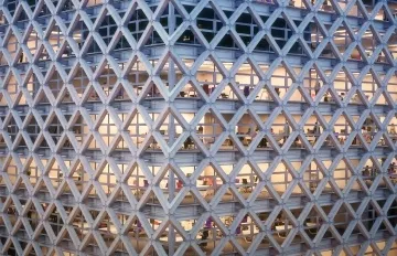
Take a simple brise-soleil for example. The two segment's shown below both use a separate material: metal for the support and wood for the shades. Each is currently a separate material, and the material ID assigned to the faces of both objects is set to 1.
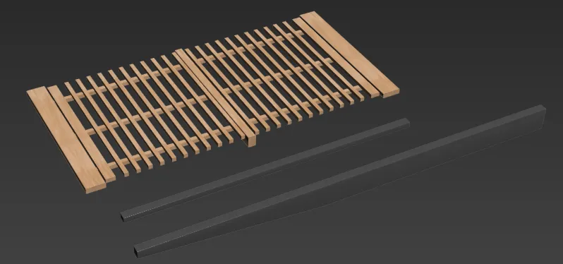
When you add these segments to RailClone, you'll notice that only the wire colour is used. This is because a material needs to be assigned to RailClone manually, but here's the problem. You have two materials on the source geometry but only one of these can be applied to RailClone, so it's necessary to a build a multi/sub object material that works when applied to all the individual segments. This will almost certainly result in needing to edit the material IDs. To illustrate this, let's fix this style.
-
Open
chapter_2_brise_soleil.maxfrom the downloads for this guide. -
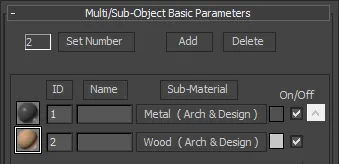
Open the material editor and create a new Multi/Sub Object material with 2 IDs. In slot 1 add the metal material, and in slot 2 add the wood material.
-
Assign the Multi/Sub-object material to the brise-soleil parts and the RailClone object. You'll notice that because everything has an ID of 1 it uses the metal material.
-
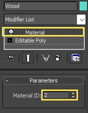
Select the wooden part of the brise soleil and add a Material modifier.
-
Change the Material ID value in the material modifier to 2 to match the Multi/Sub-Object material we just created.
-
The RailClone object updates automatically and any geometry with an ID of 2 now uses the wood material.
Tips to automate building multi-sub object materials
If you don't want to create Multi/Sub-object materials and re-assign IDs manually, an easy way to consolidate materials is as follows:
-
Attach all the objects into a single mesh. Use the default options, so Max creates the multi/sub material automatically.
-
Detach each object back into separate objects.
-
Re-adjust the pivots if necessary.
You may also find there are some scripts available that create a new Multi-Sub object material and reassign IDs for you. For example, we use RappaTools as it has a Create Multi-Material from Selection option. We believe the free version may have the same functionality, but we haven't tried it extensively. Another option is the Material Combiner script by Brian Keffer which performs a similar function.
Related Tutorials
The Populate Building interiors tutorial demonstrate how RailClone and ForestPack can be used together and also features section on creating a lattice facade that is a useful demonstration of how to create a style from minimal components using Sequence and Mirror operators.

This tutorial explains how to create a ceiling. The parts are all modelled separately based on profiles supplied by ceiling manufacturers.
For more information please see the 1D arrays - Generator L1S . 2D arrays - Generator A2S , Segments and Rendering Best Practices sections of the online documentation.