Forest LOD
Overview
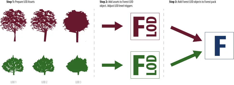
Forest LOD allows you to switch geometry objects based on their distance from the camera or their size in the render view. The most common use for this feature is to create Level of Detail models so that less complex models and materials can be used further from the camera to help speed up renders.
Using LOD models with ForestPack requires a slightly different workflow from using standard geometry objects.
-
Instead of a single model for each object, LOD models require 2 or more models. Each of these optionally can have unique materials.
-
Models are added to a Forest LOD object. From here you can configure the trigger distance or size to switch between models, assign materials and blur the transition between LOD levels.
-
Finally, the Forest LOD object is scattered by adding it to the Geometry List inside a ForestPack object. From here it is also possible to override the distances used to calculate the trigger points directly from the Camera Rollout.
Procedures
To create LODs based on distance from the camera
-
Go to Create > Itoo Software > Forest LOD and click and drag to create a new Forest LOD object in the viewport.
-
Add the objects to the Forest LOD object. To add a single object click on , select Custom Object , click
and pick an item from the scene. To add multiple objects click and pick 1 or more items from the Object Picker.
-
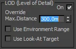
Add Visibility > Max Distance values for each LOD level. The lower the value the closer to the camera, so the more complex models should have the smaller values. See below for a more detailed explanation. Alternatively you can click to automatically create values based on the object's order in the LOD list.
-
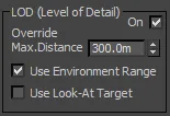
Enter a Maximum Distance value. This defines the distance range over which the LOD effect is calculated.
-
Add Variation if necessary to blur the transition between LOD levels. 6. Select or create a new ForestPack object. Go to the Geometry Rollout, click on and select the Forest LOD object from the scene. There is no limit on the number of LOD objects that can be used.
-
If you want to override the maximum distance settings, go to the Camera Rollout and increase the Max Distance value. Any value greater than 0 will override the settings used in the Forest LOD object.
To create LODs based on screen size
-
Go to Create > Itoo Software > Forest LOD and click and drag to create a new Forest LOD object in the viewport.
-
Add the objects to the Forest LOD object. To add a single object click on , select Custom Object , click and pick an item from the scene. To add multiple objects click and pick 1 or more items from the Object Picker.
-
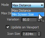
Change the mode to Min Screen Size.
-
Add Visibility > Max Min Screen Size values for each LOD level. The higher the value the closer to the camera, so the more complex models should have the larger values. See below for a more detailed explanation. Alternatively you can click to automatically create values based on the object's order in the LOD list.
-
Add Variation if necessary to blur the transition between LOD levels.

-
Select or create a new ForestPack object. Go to the Geometry Rollout, click on and select the Forest LOD object from the scene. There is no limit on the number of LOD objects that can be used.
To assign materials to LOD levels
-
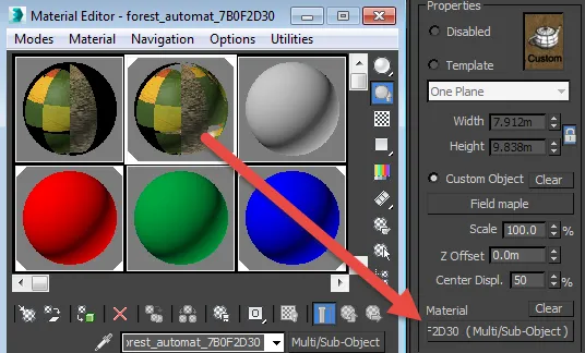
Click on an object from the LOD List
-
Drag a material from the Material Editor to the Material slot in the Properties rollout. Simpler materials would normally be used furthest from the camera.
-
Repeat for each object in the LOD List. Alternatively if you have a unique object for each LOD level, you can apply materials directly to the source geometry.
To set Maximum Distance from a camera's Environment Range
-
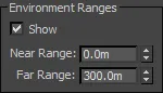
In the ForestPack object, go to the Camera rollout and turn on Use Environment Range
-
Select the camera, and you can now use the Environment Ranges values to define the Maximum Distance used to calculate the LOD levels.
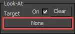
To use a Custom Look-At Target
-
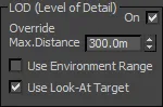
In the ForestPack object, go to the Camera rollout and turn on Use Look-At Target.
-
Assign a Look-At Target from the Look-At group
-
Adjust the Max Distance. this will now be calculated radially from the Look At object.
Interface
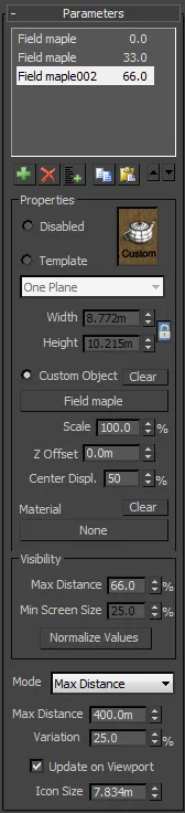
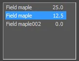
LOD List
Use this list to add LOD levels for the current object. Each item on this list represents a single LOD level. The number next to the name shows the percentage of either the distance from the camera or the screen size at which this level becomes active.
To add geometry use the following buttons:
| icon | Function |
|---|---|
| Add object to the LOD List | |
| Remove selected object(s) from the LOD List | |
| Add multiple objects to the LOD List | |
| Copy selected object(s) | |
| Paste objects(s) | |
| Move selected object(s) up/down |
Properties
Disabled
Disables geometry for the selected item. This is not the same as deleting the item, it will still be taken into consideration as part of the scatter algorithm, but will not render, leaving a space.
Template
Use a predefined geometry template from the drop-down list. Used for billboards.
Custom Object
Use a custom mesh. Click this button to select the source object from the scene. when an object is selected the button will display the source name, otherwise it will return None . To remove references to the source, click Clear.
Scale
Allows you to proportionately scale the geometry as a percentage of its original size.
Z Offset
Sets an offset value on the Z Axis, measured in scene units.
Center Displace
Adjust the lateral pivot position. Useful when using billboards which can rotate on the Z axis to keep them facing toward the camera. Use this value to adjust the rotation point for textures that require an offset pivot.
Material
Used to assign a material to the selected item. Each LOD level can use a different material
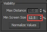
Visibility
The visibility group is used to control the point at which the LOD object switches between levels.
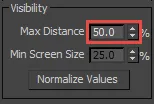
Max Distance
Used to set the trigger distance for each LOD level. Measured as a percentage of the Maximum Distance value. An object is used when it exceeds this distance. If more than one LOD is eligible, the one nearest the current distance value is used.
Min Screen Size
Used to set the trigger size for each LOD level. Measured as a percentage of screen size as viewed from the active camera. An object is used when its size exceeds this value.
Normalize Values
Click this to automatically assign values to Max Distance or Min Screen Size for all LOD levels. This function used the order of the objects in the LOD list to automatically calculate evenly distributed values.
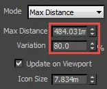
Mode
There are two modes:
-
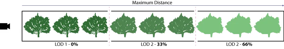
Maximum Distance. this is the default mode and uses a distance measured in scene units radially from the active camera, or optionally a manually assigned custom look-at target. An LOD level is triggered when its distance from the camera exceeds the percentage specified by the Visibility > Max Distance value. In the illustration below LOD 1 is set to 0% so displays immediately. LOD 2 is set to 33% and so becomes active and replaces LOD 1 when an object's distance from the camera is a third of the maximum distance. Finally, all objects displayed further than 66% of the maximum distance from the camera are replaced with LOD 3.
-
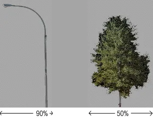
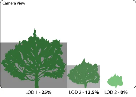
Minimum screen size: this mode use the scatter object's size in the camera view to switch between LOD levels. This is measured by comparing the diagonal length of the bounding box to the diagonal length of the screen. In the illustration below LOD level 1 is set to appear only if the tree's diagonal length is greater than 25% if the screen's diagonal. LOD 2 appears if the diagonal is below 25% but above 12.5% and finally LOD 3 will appear when it's diagonal length is below 12.5% to infinity.
Variation
Use this to add randomness to the Maximum distance or screen size settings creating a blurred boundary between LOD levels. This helps to disguise the transition from one LOD level to another and reduces obvious popping when rendering animations.

Update on Viewport
When On, LOD effects will be visible in the viewport. When off LOD effects are only visible at render time.
Icon Size
Used to set the size of the Forest LOD icon.