Image Mode
Overview
This mode allows the user to specify a map to define the distribution of trees within the inclusion area.
To allow for the most flexibility an image is used as a distribution map. Each pixel in the image represents a potential tree position, a white pixels adds a tree, a black pixels leaves a space.
Using this method, it's possible to define nearly any distribution, from random scattering to very regular groups. In addition, it is possible to choose which objects are placed either using built-in clustering algorithms or using a colour map.
Interface
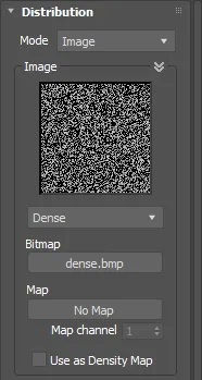
Image Settings
ForestPack can use a bitmap or a map as distribution image.
The plugin comes with several standard bitmaps included. A custom bitmap can be selected as well by clicking the button under "Bitmap". The list of bitmaps is user customizable. In C:\Program Files\ItooSoft\forestpackpro\distmaps, there is a text file named "index.dat". It includes a list of the bitmap names and the associated file names.
To use a map, click the 'Map' button and select it from the Material/Map browser. All Max texture types are supported, from static bitmaps to animated noise maps as long as they can be generated before render time. Use the "Clear" button to remove a map.
The Use as Density Map option allows you to reinterpret the Distribution Image as a grayscale density map instead of
a simple black/white bitmap.
This provides finer control over scatter distribution by using pixel intensity values to modulate the density of
scattered objects.
The "Map channel " parameter is described in the following section.
Density
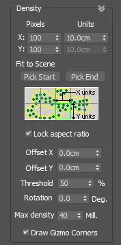
Lets the user choose the scale of the distribution map in the scene. The map is applied in a manner similar to the way texture maps are applied in Max. The image is scaled according to the defined size, and tiled in all directions.
It's important to remember that the perimeter of the forest is always defined by a spline boundary or surface. The distribution map only shows how the trees are arranged within zone.
X/Y Units
Defines the size of the distribution map in scene's units. If we use small values, we will see how the density of trees and the number of trees grows. Also, the process time and geometry size of the Forest object is higher. The plugin is optimized for speed, but to further speed up the plugin, here are some recommendations:
- If the bitmap has fewer white pixels (less trees) but you set lower X/Y values, the density will be very high but most of the processing time will be wasted in computing gaps. To increase the density of trees, first set a higher density map, then lower the X/Y parameters. You can see in real-time some build parameters (such as density, number of trees) using the "Forest Stats" window. Open it clicking the "View Stats" button in the "General" rollout.
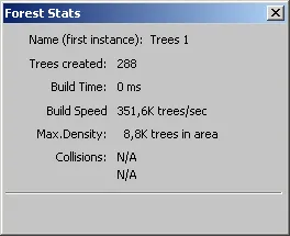
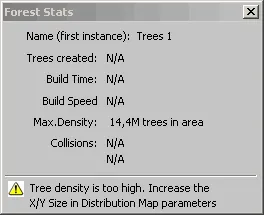
The "Stats" windows also alerts the user to some warning conditions such as when the area spline is not assigned, if the density is too high and other conditions.
- There is a limit for the number of trees created in a Forest object. This parameter is defined in the "Display" rollout, and the default value is 500,000. Also, when the resulting mesh has more than 100,000 faces, ForestPack builds the trees for the viewport using a simplified geometry (adaptative display mode). All these behaviors are adjusted in the "Display" rollout.
X/Y Pixels
These values are used to adjust the density in procedural maps, without modifying the X/Y Units scale. These parameters are locked when using bitmaps, using the number of pixels of the image as default value.
Image->Map Channel
As alternative of using the X/Y values to define the density of the distribution map, it's possible to get the scale from the UV coordinates of the surface. This mode is useful to adjust the position of trees in more precise way, using a surface map as reference.
To use this mode, a surface object must be assigned in the "Surface" rollout. The Surfaces can work in two operation modes, XY or UV (defined in the Surface rollout):
- XY mode: you can use any map channel assigned to the surface and combine composited maps that use multiple map channels as required.
- UV mode: the map channel used is specified by the Map Channel parameter, multiple channels are currently not supported.
Fit to scene
Allows the user to fit the map exactly over a position on the scene, automatically adjusting the offset and size values. Use Pick Start/Pick End to select on the scene the position of two opposite corners of the map. This tool is useful for adjusting maps which represent exact positions of elements in the image, such as modified aerial views using a white pixel per tree.
Lock Aspect Ratio
Locks the X/Y aspect of the map. When this checkbox is enabled, the Y size for map is ignored and only the X value is used.
Offset
Adjusts the offset of the map over the scene. Values are in the scene's units.
Threshold
Defines how the image pixels are converted to black/white levels when the bitmap is in grayscale or color mode.
Rotation
Rotates the distribution map a specific number of degrees.
Max density
Set the limit of possible tree positions in the area (by default 10 million). Take care: this includes both white and black pixels in the distribution map, so you may reach the density limit using an empty map and low X/Y values, but not get a single tree in the scene.
Draw Gizmo Corners
Draws the corners of the distribution map to adjust it more easily.
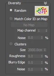
Diversity Settings
This window defines different modes to select what type of object, from all items defined in the Geometry List, is used when planting a tree for each pixel of the Distribution map.
Random
Creates plants randomly, using the "Probability" values of the Geometry List. This is the default mode.
Match Color ID on Map
This mode allows you to use coloured distribution maps, where the color of each pixel defines a type of plant. In the scattering process, each pixel of the map is matched with the "Colour ID" values of the Geometry List, taking the most similar.
Note: the "Probability" values of Geometry List items are ignored on this mode.
Although it's not necessary that colors are exact, to get the best results is recommended that "Color ID" values are the most similar possible to those used in the map. Also is better to use high contrast colours as red, blue, yellow, green... The gaps (empty positions) can be defined by assigning a specific colour with a "Disabled" item of in the Geometry list.
The "Noise" parameter is used to add some random variation to the distribution.
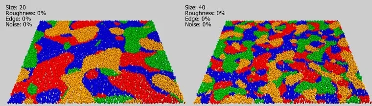
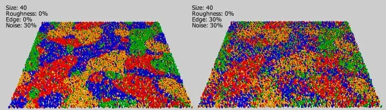
Clusters
This mode works grouping items of same type, in a similar way that plants are found in the nature. These groups are called clusters.
The following parameters are used to define the cluster appearance:
- Size: use it to adjust the size of the clusters. This value is expressed in scene's units.
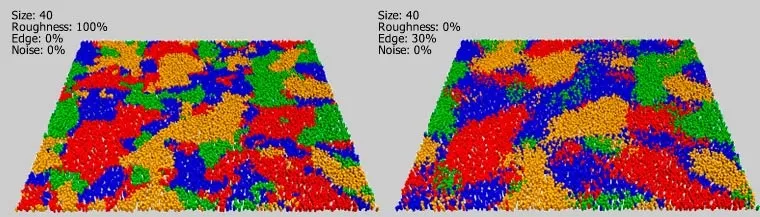
- Roughness: set the shape of the cluster (0% = smooth, 100% = rough).
- Blurry Edge: modifies cluster edge from sharp (0%) to blurred (100%).
- Noise: adds random items to the distribution (0% to 100%).
Clusters require to use more than one item in the Geometry List. If not, it has no effect.
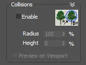
Collisions
This feature checks the collisions between trees. It works by scattering the items, and then deleting those trees that collide with their neighbors.
Collision checking is based on exploring possible intersections between virtual bounding-spheres that surround each object.
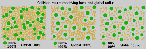
To get the sphere's size of each objet, two parameters are used: Geometry Rollout->Radius, that is defined by each item of the Geometry List, and Distribution Map->Radius, that is a gobal value for the Forest object. Both parameters are multiplied to get the resulting size. The value is defined in percentage of tree's size (from 100% to 1%).
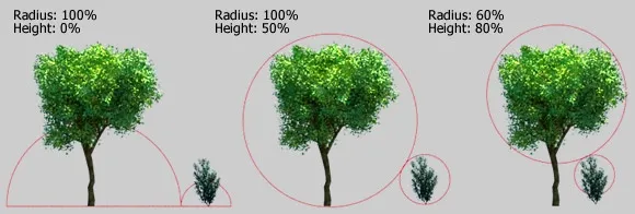
The "Height" value is used to define the sphere's center in Z axis. The default value (0%) builds the sphere at ground level, increase it to improve the collision detection when using tall trees with large treetops.
Take care when using Collision Detection: if you increase the density of trees (using a dense map or lowering the X/Y parameters), you may get the same number of trees, because most of them are discarded by collisions, but the plugin will have an extra workload in order to process them. This condition is alerted in the Forest Stats window, when the number of discarded trees is greater than 50%.