Create your first 2d array
The 2D Array , or A2S generator, features 12 possible inputs, making it an incredibly powerful and versatile tool for creating parametrised objects including façades, floors, ceilings, pavement, tiles, structural steel, cladding and much more. Before creating your first style, take a few minutes to get reacquainted with the different parts of the A2S Array. The exercise on this page makes use of all 12 inputs, but often you'll only need a selection of these to get the correct result.
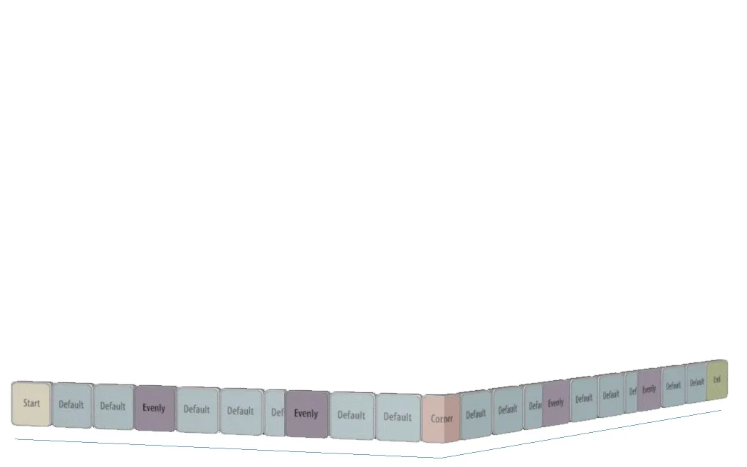
This generator can be confusing for new users, but once you've understood the L1S generator, the A2S generator becomes a lot easier. The best way to understand the nuances of the A2S generator is to think of it as a stack of L1S generators. Internally, each row is treated as an independent 1D array, each with its own start, end, corner and evenly segments. The A2S array uses 4 types of row: one at the Bottom if the array, one at the Top several spaced Evenly in the Y axis, and a Default row that fills in whatever is left between the other 3. Each of these rows independently behaves exactly like an L1S generator, but the inputs are renamed. The animated gif and table below demonstrate the relationship between a stack of L1S arrays and the input names as they appear in the A2S generator
| L1S Row | Start | Corner | Evenly | Default | End |
|---|---|---|---|---|---|
| Top Row | Top Left Corner | Inner Corner | X Evenly | Top side | Top Right corner |
| Y Evenly Row | Left side | Inner Corner | X Evenly | Y Evenly | Right side '*' |
| Default Row | Left side | Inner Corner | X Evenly | Default | Right side |
| Bottom Row | Left Bottom corner | Inner Corner | X Evenly | Bottom row | Right Bottom Corner |
(for Y Evenly if extend to side is active)
Creating Geometry for an A2S Generator
At the beginning of the previous chapter we discussed the importance of planning your geometry to ensure it fits correctly into the different parts of the array. The same rules apply, and are even more important when creating geometry for the A2S array. To recap, the best way to understand the A2S generator is to think of each row as a separate L1S generators, each once stacked on top of another, but all still essentially independent.
This understanding is essential if you want to create geometry to populate an array that is intended to fit together perfectly without leaving any gaps.These are the 3 Golden rules for modelling for the A2S Generator.
Rule 1: Segments can be any length
As we've seen, each Row is a separate L1S generator and is calculated independently, so there's no problem at all with using segments with unequal sizes on the X axis. Adjacent segments in the same row will simply move along the array to accommodate any size of geometry. Rows above and below remain unaffected and no gaps appear.
Rule 2: To avoid gaps, Segments should be the same length
Because the A2S array is a stack of L1S generators, if you use Segments with unequal sizes on the Y axis in a row, the overall height of that row is determined by the tallest segment. The row directly above will be positioned after the tallest segment and gaps will appear.
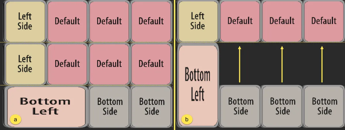
a. The corner segment has been scaled to twice it's normal width, adjacent segments in the same row adjust automatically and no gaps appear | b. The corner segment has been scaled to twice it's normal height, the row above moves to accommodate the largest size and gaps appear in the array.
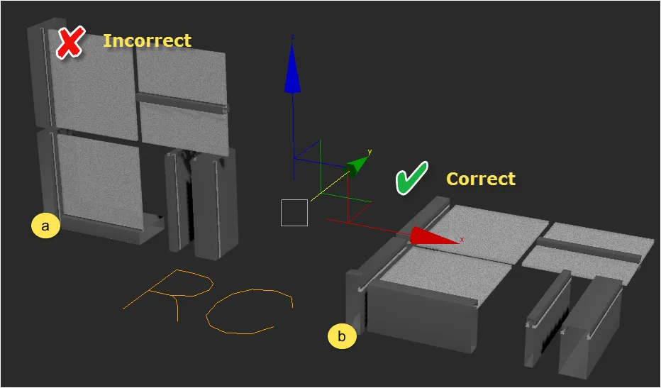
Rule 3: Align the source geometry's pivots to the X and Y axes
The 2d array is created along the X and Y axes of the RailClone object's local coordinate system, and segment's will be oriented to that their own axes align with this. It's very tempting, especially with vertical styles like façades and cladding, to align geometry incorrectly so that the vertical elements are on the Z axis. For example, the image below illustrates the segments used in the façade exercise on this page. The collection of segments marked "A" are incorrectly orientated so that there verticals align to the Z Axis. The group of segments marked B are correctly oriented. Their segments are aligned to the X and Y axis, matching the axes used by RailClone to construct the array.
Exercise: Creating glazing using a 2D Array
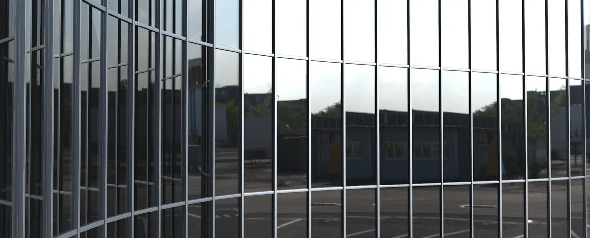
In this exercise you'll create a new glazing style from scratch that uses all 12 inputs of the A2S generator. By doing this you should gain a good understanding of the A2S generator.
Creating a Generator
To create a generator for the Glazing , follow these steps:
-
Open the file named A2S_generator.max. This scene contains all the geometry and paths required to recreate this style.
-
Create a new RailClone object and name if rc_glazing.
-
Go to the Modify Panel, open the Style rollout and click on
 to open the Style Editor.
 -
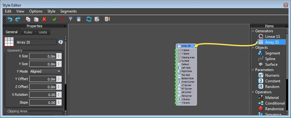
With the Style Editor open, drag an Array 2S Generator from the Items Listto the Construction View.
-
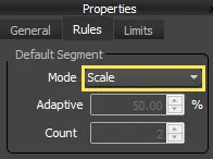
Open the Generator's properties and set the Rules > Default Segment > Mode Type to Scale.
Adding Base Objects
Now that you have an array, you need to specify how large it should be. To create a A2S array you need to set a distance for the X and Y axes. There are two ways do this, you can either specify a distance value in scene units, or use a spline. In this example you'll use a spline or the X axis and use a distance for the Y axis:
Add a spline for X Axis
-
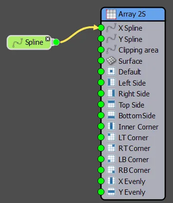
Drag a Spline Object from the Items List to the Construction View.
-
Click and hold on the Output if the Spline node and drag a wire to the X Spline Input if the generator.
-
We now need to tell RailClone which spline in the scene to use. You can select the spline in one of two ways:
Either from inside the style Editor...
-
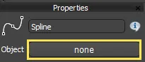
Select theSpline node and go the Properties Panel.
-
Click the Object Picker button.
-
Click the spline in the scene called Path Spline.
...or from the Modify Panel
- Open the Base Objects rollout in the Modify Panel.
- Select Spline from theBase Objects list.
- Click on the Spline picker button and select the spline called Spline 01 from the scene.
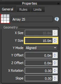
Set a distance for the Y axis
- In the Style Editor click on the Generator node.
- Go to the Properties Panel.
- Enter a distance value of 10m for the Properties > Geometry > Y Size parameter.
Importing Segments
The Glazing style is constructed from seven different segments. Adding these one at a time is time-consuming, so to speed things up we'll automate the process using RailClone's Clone Multiple command.
-
Create a new Segment Object.
-
Go to the Properties Editor and click on the Object picker.
-
Pick the object named Default from the scene.
-
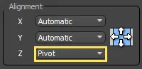
Still in the new Segment node's Properties, change Alignment > Z to Pivot. this is to ensure that the glass and the seals and glazing bars align correctly.
-
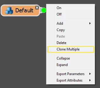
We can use this node as a template to add the other geometry object. These will inherit the Alignment properties set in the previous step. To do this right-click on the new Segment and select Clone Multiple.
-
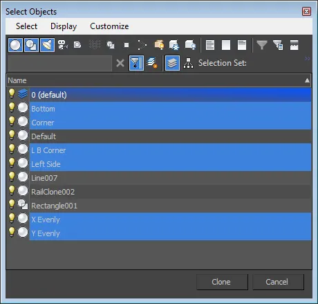
A Select Objects window opens. Pick Bottom Corner, LB Corner, Left Side, X Evenly, Y Evenly, and then click Clone, RailClone will generate a new Segment node for each of the selected items.
Adding the Corners
Before we attach the segments to the generator, note that we have four corners but only one segment. In this section we'll demonstrate how you can re-purpose geometry by using the Mirror operator to flip the left bottom segment to create the missing corners.
-
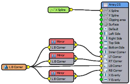
Wire the Segment name L B Corner to the LB Corner input of the generator.
-
Create a new Mirror operator. Wire the L B Corner segment to the Mirror operator's input, and then wire the Mirror operator's output to the RB Corner input of the generator. The mirror operator has flipped the segment on the X Axis.
-
Next we'll create the top corners. Create a second Mirror operator and open the Properties Panel. Change the Axis to Y.
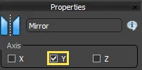
-
Wire the L B Corner segment to the new Mirror operator, then wire the Mirror operator to the LT Corner input of the generator. The mirror operator has flipped the segment on the Y Axis. 5. Create a third Mirror operator and open the Properties panel. Change the Axis to X and Y.
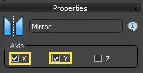
-
Wire the L B Corner segment to the third Mirror operator, then wire the Mirror operator to the RT Corner input of the generator. The mirror operator has flipped the segment on the X and Y Axis, completing the corners. At this point your Node tree should look like this
Adding the Sides
Now we'll add a frame to the Top, Bottom left and Right of the glazing. Once again you'll use the mirror operator to re-use segments.
-
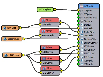
Wire the Segment named Left to the Left input of the generator.
-
Create a new Mirror operator. Wire the Left segment to the Mirror operator and then wire the Mirror operator to the Right input of the generator.
-
Wire the Segment named Bottom to the Bottom input of the generator.
-
Create another Mirror operator and open the Properties panel. Change the Axis to Y.
-
Wire the Bottom segment to the new Mirror operator, then wire the Mirror operator to the Top input of the generator. At this point your Node tree should look like this
You will have a frame running around the exterior of the array. In the next step we'll start to fill in the centre.
Adding Evenly spaced segment on the X Axis
Segments added to the X Evenly input are regularly positioned along the X axis of the array. Follow next few steps to use this to add vertical separators to the glazing style.
-
Wire the Segment named X Evenly to the X Evenly input of the generator. You'll see regularly space vertical appear in the array.
-
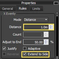
To control the spacing between Evenly segments, select the Generator and go to Properties > Rules > X Evenly and enter a Distance value of 1m.
-
Ensure that Extend to Side is activated. This will ensure the Evenly segments go to the edges of the array.
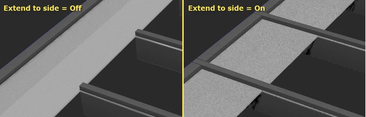
When the "Extend to Side" check-box is enabled for any of the X Evenly, Y Evenly or Inner Corner inputs, The geometry is extended the sides of the array cutting through any segments being used in the Left, Right, Top or Bottom inputs.
Adding Inner Corners
Inner Corners in an A2S generator behave exactly like the Corner input of the L1S Generator. Both of these add geometry
only on vertices of a specified type found on the path. By default, only Corner or Bezier-Corner vertices are used, but this can be changed in the Generator's properties.To add corners to our Glass Wall style:
-
Wire the Segment named Corner to the Corner input of the generator.
-
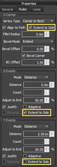
Open the Generator's properties and ensure that Rules X > Corner > Extend to Side is activated. This will ensure the corner segments go to the edges of the array.
-
Turn on Bevel Corner and set the BC Offset value to 5%.
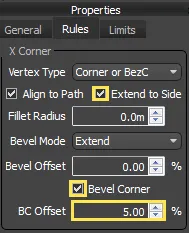
Bevel Corner Offset allows you to adjust the offset of the Corner segments. The distance is measured as a percentage of the length of the corner segment. positive values pull the segment towards the corner, negative values will move the segments away from the corner.
Creating Evenly spaced segments on the Y Axis
Segments added to the Y Evenly input are regularly spaced along the Y axis of the array. Follow the next few steps to use this to add horizontal separators to the glazing style.
-
Wire the Segment named Y Evenly to the Y Evenly input of the generator. You'll see regularly space horizontal bars appear in the array.
-
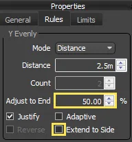
To control the spacing between Y Evenly segments, go to the Generator's Properties and enter a Y Evenly > Distance value of 2.5m.
-
Ensure that Extend to Side is unchecked. In this case we want to prevent the Y Evenly segments from extending to the sides of the array.
Adding Default segments
Finally, we'll fill in the remaining gaps with the default segment.
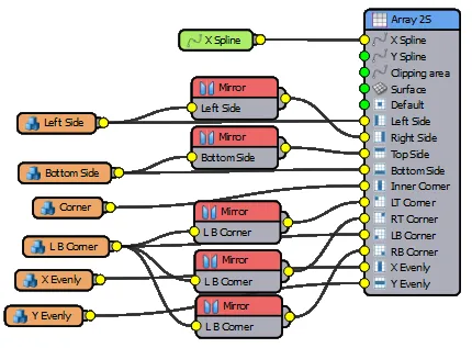
-
Wire the Segment named Default to the Default input of the generator. You've now used all 12 inputs of the A2S generator to create an adjustable glazing style try experimenting with the Evenly distances to get different results. The final node tree should resemble the image below
Adjusting Padding
You may have noticed If you look closely at the style you'll that there are some unwanted gaps between the horizontal and vertical elements.
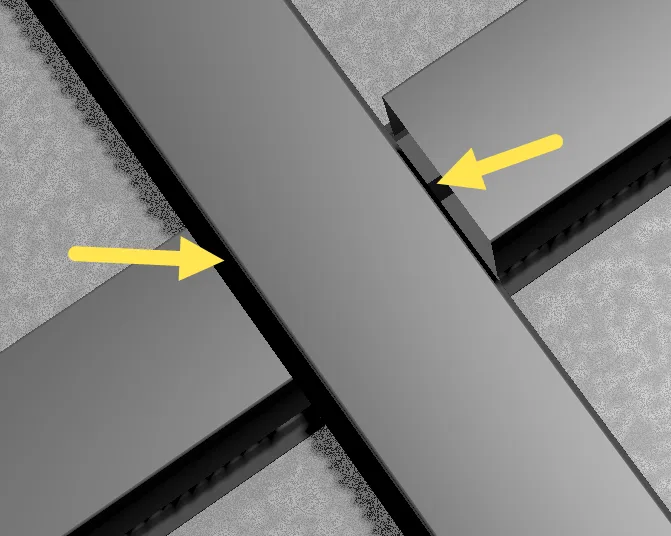
These gaps are caused by the rubber seal which extends beyond the metal frame. To correct this we need to add some padding values to the Vertical elements. For a more detailed explanation of padding, please see the chapter called 11 - How to align, overlap and transform geometry
-
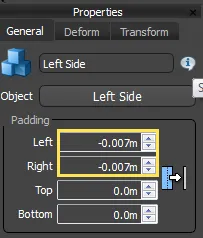
Select the Left segment and open the Properties. Enter a value of -0.007m for the Left Padding and Right Padding parameters.
-
Repeat this procedure for the X Evenly, L B Corner, and Corner segments. The gaps will now be removed.
Rotate the Array
This completes the style though it is currently flat on the ground plane. For a glazing style we need to rotate the entire mesh so that it is vertical. To do this:
-
Select the Generator and open the Properties.
-
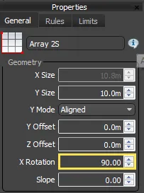
Enter a value of 90 degrees for the General > X Rotation parameter.
-
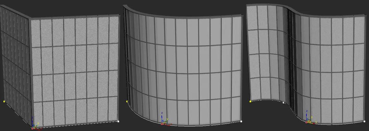
You can now try reshaping the spline to get different shapes of glazed wall.
Related Tutorials
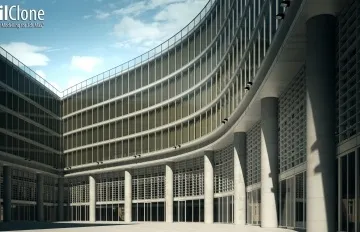
Create a curtain wall building
A further example of using the A2S array to create a curtain wall. In this example we do things slightly differently and use a Spline for both axes of the array, making it possible to create double-curved façades.

In the final part of the stadium tutorial we demonstrate how to use an A2S generator to create the roof. You'll learn how to create the style and also export attributes so that you can adjust the depth of the roof and spacing of the supports from the Modify panel

In the last 2 parts of this tutorial we explain how to use the A2s generator to create a paving style and a huge sea wall using RailClone's formidable instancing power to create the geometry from individual bricks!
For more information please see the 2D arrays - Generator A2S section of the online documentation.