Create your first 1D array
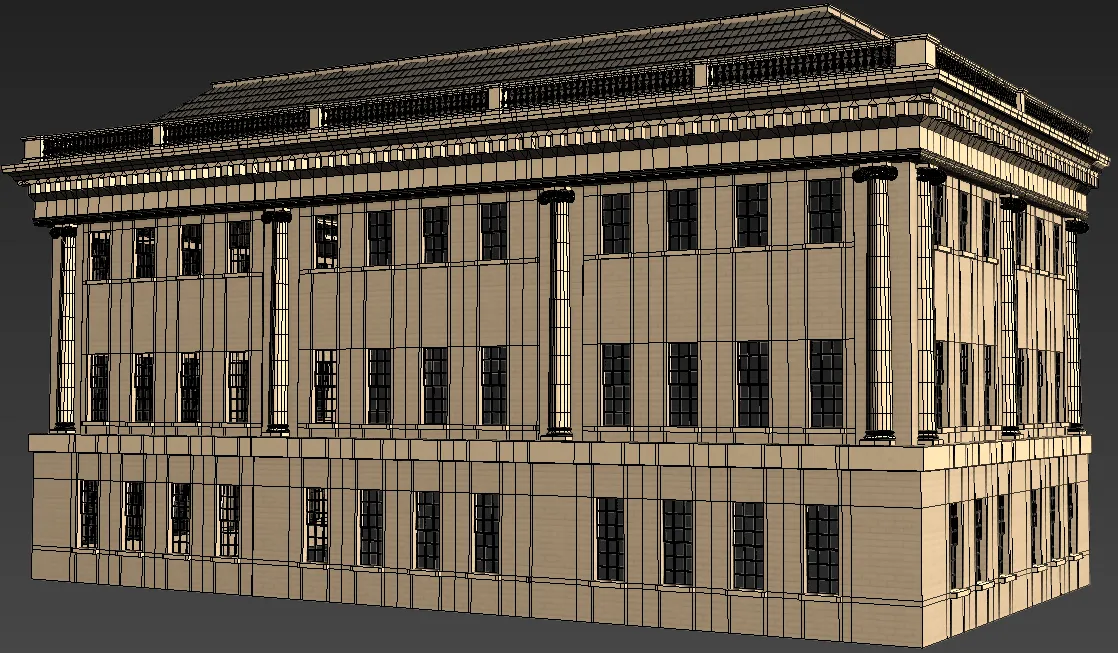
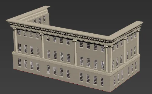
Having learned how to use and adapt the library, it's time to start creating your own styles. To do this it's important to have a good understanding of how base objects, segments and generators interact. In this section we'll learn how to use an L1S generator to create a low-poly background building.
To get the assets required to follow this chapter, download and open l1s-exercise.max.
Creating geometry for an L1S Generator
The first thing to consider when creating a new RC style is how the individual pieces of geometry fit together. In Chapter 4 we examined the five parts of a one dimensional array, and when creating the meshes for segments it's important to think in terms of how they will fit into this system. You may find it is helpful to model a small part of the style as a single object and then break it apart using 3ds Max's Slice modifier, doing this will ensure that the resultant segments fit together correctly. Illustrated below are the pieces that you will use for the exercises in this chapter. The Walls and Balustrades were created using the Slice-modifier technique.
Balustrades
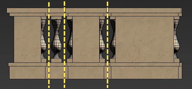
Balustrades model before slicing - yellow lines indicate slice planes
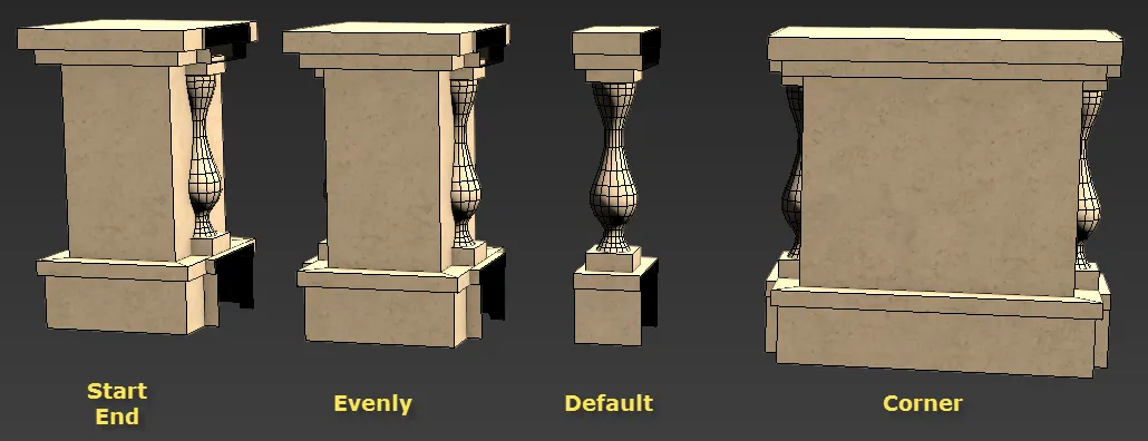
Balustrades model after slicing.
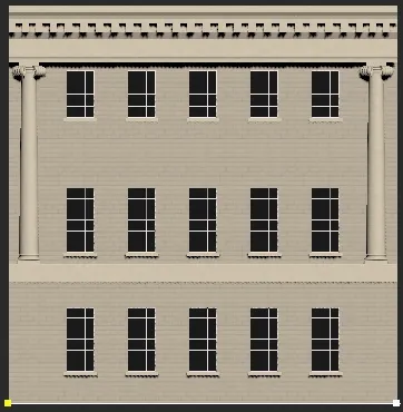
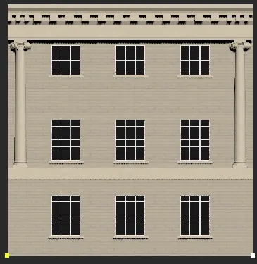
Walls
Walls after slicing.
Roof
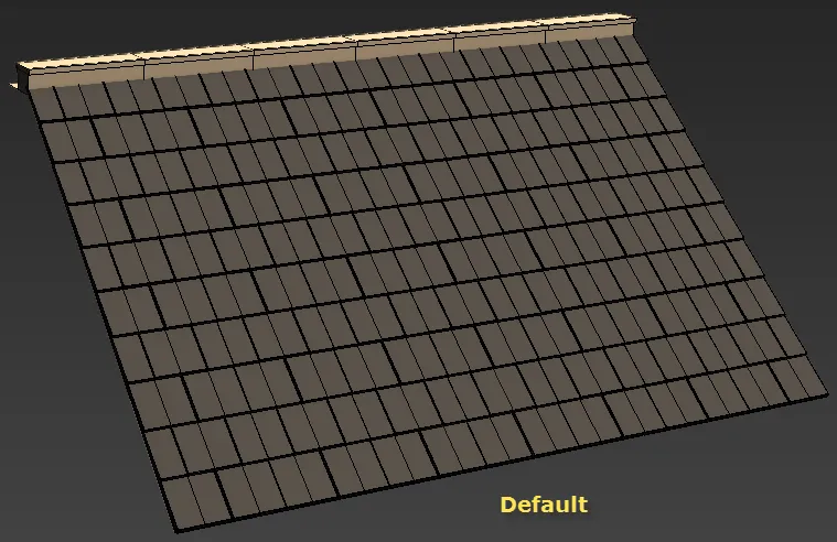
The roof using only one segment
Pivots
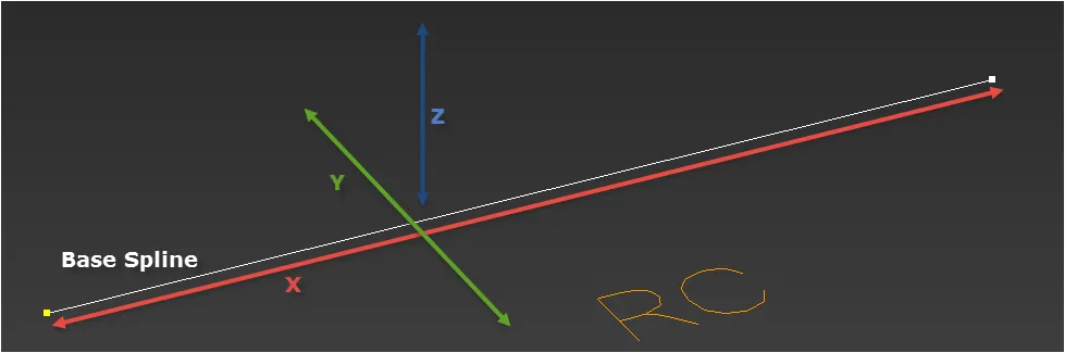
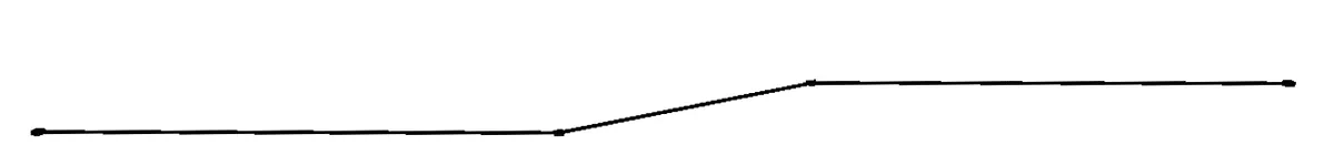
The geometry's pivots will be aligned with the coordinate system used by the RailClone object. In an L1S array, and when creating the RailClone object in a Perspective or Top viewport, the axes are oriented so that the X Axis follows the length of the spline, the Y Axis runs perpendicular to the spline, and the Z Axis is vertical, matching the world's Z axis and also the RailClone object's local orientation.
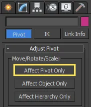
In order for geometry to be correctly aligned in the array, it may occasionally be necessary to adjust the orientation of the local axis. To do this:
-
Select the Geometry object.
-
Go to 3ds Max's Hierarchy Panel.
-
Click Affect Pivot Only.
-
Rotate the Gizmo to the correct orientation.
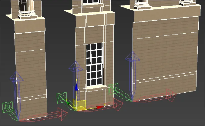
As well as orientation, another consideration is the position of pivot points. In order for segments to snap together correctly, it's possible to align the segments on the base object using the local pivot point of the source geometry. This is particularly true on the Y and Z axis, and less so on the X where RailClone's automatic mode is often more useful. In the examples on this page we will use the pivot point to position the all the segments on the Y axis and ensure they snap together correctly, to make this possible all the pivot points are aligned on the X and Y axes as illustrated in the image below.
Material IDs and UVW Coordinates
By default, RailClone retains the UVW coordinates and Material IDs of the source geometry. It does not automatically create multi-sub object materials or reassign IDs. This means that when creating geometry it is important to ensure that the Material IDs would work as if the individual components were a single object with a single material (which can be a mult-sub), since this is how they will appear to RailClone.
Exercise: Creating A Rule-Set
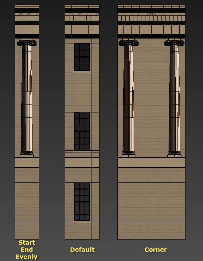
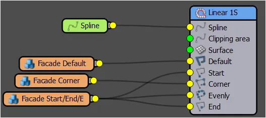
As you saw in Chapter 3, the L1S generator has 5 inputs: Start, End, Corner Evenly, and Default.
In this section we'll create an example that uses of all of these. It's important to note that it isn't necessary to use all 5 inputs, many styles may only require a selection of the available inputs. When an input is omitted the array is completed using Default segments.
Creating a RailClone Object
Once the geometry has been prepared, we're ready to create a new style. To do this we need to add a new empty RailClone object and open the Style editor:
-
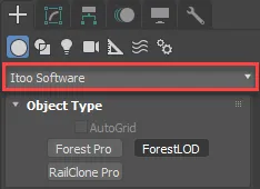
Go to 3ds Max's Command > Create > Geometry Panel and change the category to iToo Software.
-
Click
 .
. -
Click and drag in the Top or Perspective viewport to create a RailClone icon.
-
Open the Style rollout and click
 to open the Style Editor.
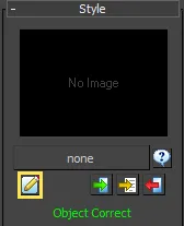 .
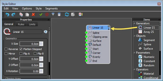
.The Style Editor will open.
Before creating your first style, take a few moments to learn how to interact with the style editor. As well as the essentials, you will learn a few lesser known commands that can make working with RailClone much faster.
-
To add a new node to the Construction view
Adding a new node
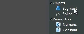
- Identify the node type in the Items list on the right hand side of the style editor, select and drag it into the Construction View.
-
To rename a node
- Select the node in the Construction View. In the Properties Editor Type a new value in the name field.
-
To connect nodes
Connecting nodes
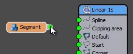
- Click on the output of a node, drag the mouse (you'll see a wire following the mouse pointer) and release over the input of another node.
-
To connect multiple nodes
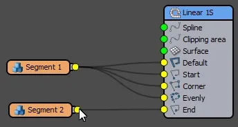
Multiple nodes can be attached to Compose, Sequence, Random, and Selector operators. To do this:
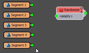
- Select the nodes you wish to attach.
- Drag any of the node's outputs to the operator's input.
-
To swap the connections for two nodes
- Drag the output of a node 1 to the output of node 2. Their connections will swap.
-
To disconnect nodes
- Click on the output slot of a node and drag to an empty area of the Construction View. Any nodes connected to the slot will be released.
-
To collapse and expand nodes
Collapsing and expanding nodes
- To collapse a node, click on the small upward facing arrow on the right of the title bar
- Once a node is collapsed, to expand it again click on the small downward facing arrow on the right of the title bar
-
To automatically select a node's children
- Hold down Alt and Click in any node to automatically select its children.
Creating a Generator
Think of a generator as the brain of the style, it creates the rules that tell RailClone how to construct the array. A style needs at least one generator but is not limited to this, you can combine as many as necessary even mixing L1S and A2S generators to rapidly achieve sophisticated results. By the end of this example you'll create a total of 3 L1S generators; one for the façade, one for the balustrade, and one for the roof.
To create a generator for the façade, follow these 2 steps:
-
With the Style Editor open, drag a L1S Generator from the Items List in the Construction View.
-
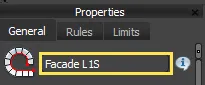
As we're going to add 2 further generators, let's name this one for easy identification. Select the node, go to the Properties Panel and enter Façade L1S in the Name field.
Adding a Base Object
Now that you have an array, you need to specify how large it should be. There are two ways to set the dimensions of an array: you can either specify a distance value in scene units, or use a spline. To set a value:
-
Click on the Generator node.
-
Go to the Properties Panel.
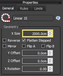
-
Enter a distance value for the Properties > Geometry > X Size parameter.
Alternatively, as in this example, you can use a spline to determine the size and path of the array. In RailClone terminology we call a spline used in this way a Base Object When using dimensions the array is always straight, but when using a spline, the array can follow and deform along complex curves. To add a spline Base Object to the generator created above, follow these steps:
-
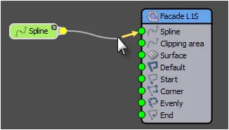
Drag a Spline Object from the Items List to the Construction View.
-
Click and hold on the Output if the Spline node and drag a wire to the Spline Input if the generator.
-
We now need to tell RailClone which spline in the scene to use. You can select the spline in one of two ways:
From inside the style Editor
-
Select the Spline Node and go the Properties Panel.
-
Click theObject Picker button.
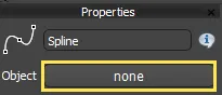
-
Click the spline in the scene called Spline 01.
From the Modify Panel
When an object node is created in the Construction view, a corresponding item is added to the Base Objects rollout in the Modify Panel. This allows you to apply the style to a spline without having to open the style editor. To do this:
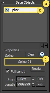
- Open the Base Objects rollout in the Modify Panel.
- SelectSpline from the Base Objects list
- Click on the Spline picker button and select the spline called Spline 01 from the scene.
Adding Segments
With a generator path successfully created, the final ingredient is geometry. In RailClone terminology, an individual mesh object added to a style is called a Segment and they are created in much the same way as base objects. To create a segment you first add a Segment node to the construction view and then assign an object from the scene. To add the first segment, follow this procedure:
-
Create a new Segment Object (
 )by dragging from the Items List to the Construction View.
 -
Go to the Properties Editor and click on the Object picker.
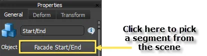
-
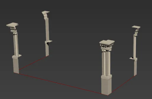
Select the geometry you wish to use from the scene, in this case we'll pick Facade Start/End/Evenly.
The Start and End input
Now that we have a segment, we need to assign it to a part of the array. In this section we'll add the segment to the Start and End inputs. Wiring a segment to these inputs creates geometry at the start and end of the path, as defined by the spline's original vertex numbers.
-
Click and hold on the Segment node's output socket, then drag a wire to the Generator's Start input socket.
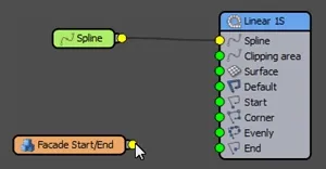
-
Repeat the action to attach the Geometry node to the Generator's End input.
-
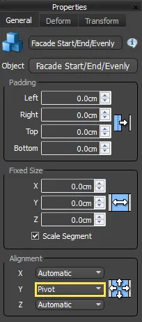
Click on the Geometry Node, go to the Properties panel and change the Alignment > Y to Pivot as mentioned in the geometry section above, to ensure that the segments fit together correctly all the segments used in this style will use Alignment > Y = Pivot.
-
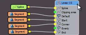
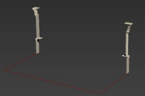
You will now have a segment at the start and end of the Spline:
Sometimes you need to assemble several segments for each position, not only one piece. In this case, you can use a "Compose" operator, to join several elements in a unique segment. We examine this in more detail in Chapter 11.
The Corner input
To create corners, we wire a segment to the "Corner" connector on the generator's nod
e. Corner geometry appears only on vertices of a specified type found on the path. By default, only Corner or Bezier-corner vertices are used, but this can be changed from the Generator's properties. In this example we'll retain the default settings.
-
Create a new Segment Object
by dragging from the Items List to the Construction View. -
Go to the Properties Editor and click on the Object picker.
-
Pick Facade Corner from the scene.
-
Still in the new Segment node's Properties change Alignment > Y to Pivot.
-
Wire the Segment to the Generator's Corner input.
Bevelling corners
By following the previous steps, the corners appear, but they look a little strange:
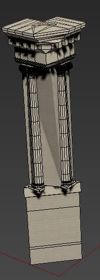
This is because by default corners will try to deform to follow the path, so the geometry is attempting to bend around a 90-degree corner. Instead, we want the corner to be bevelled To do this make these changes:

-
Select the Generator and go to the Properties Panel.
-
Click the Rules tab.
-
Activate the Bevel Corner checkbox.
-
The segments are now sliced on the corner. You can adjust this further using the BC Offset value which allows you to add an offset to the Corner segments. Positive values pull the segment towards the corner, and negative values move the segments away from the corner. For this example enter a value of 35% to ensure that the Corner segments bevels in the correct place.
-
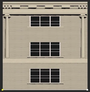
You have now successfully added Start, End and Corner segments to the array:
The Evenly input
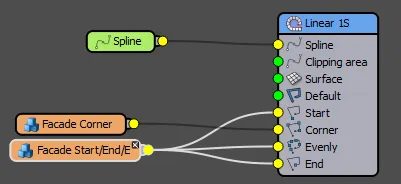
This construction rule lets you add regularly spaced segments along the path between Start, End and Corner segments. In this example you'll reuse the existing segment named Facade Start/End/Evenly.
-
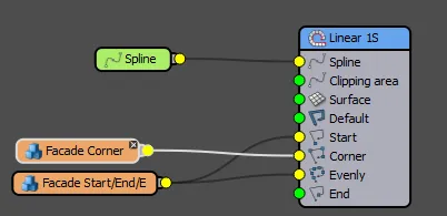
Wire the segment named Facade Start/End/Evenly to the Generator's Evenly input.
-
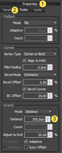
To change the spacing between Evenly segments, go to the Generator's Properties(1). Click on the Rules tab (2) and edit the Evenly > Distance value (3). For this example enter a value of 700cm.
-
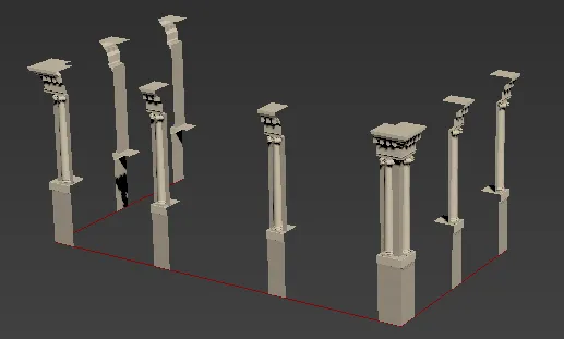
You have now successfully added Start, End, Corner and Evenly segments to the array. There's only one more input left to add - Default.
The Default input
The segment used in the default input fills in between the Start, End, Corner, and Evenly segments.
To add a Default segment:
-
Create a new Segment Object (
)by dragging from the Items List to the Construction View. -
Go to the Properties Editor and click on the Object picker.
-
Pick Façade Default from the scene.
-
Still in the new Segment node's Properties change Alignment > Y to Pivot.
-
Wire the new segment to the Generator's Default input.
-
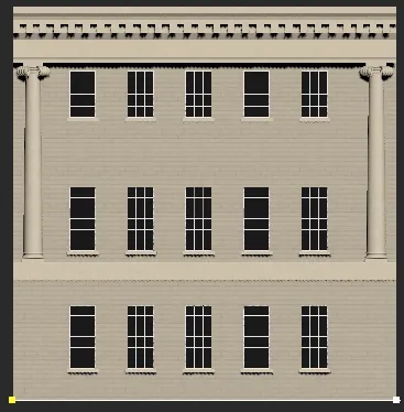
You have now successfully added Start, End, Corner and Default segments to the array and completed the façade. In the next sections you add additional generators to create a balustrade and roof.
Though in this example the default segments simply tile along the path, RailClone has 3 additional modes for calculating how to fill a section with Default geometry:
Tile (Default)
The default segment are replicated along the path, slicing the geometry if necessary.
Scale
The default segments are scaled along the X axis to fit the distance between the initial and final positions of the path section. A section is defined by the Start and End points of the spline unless an X-Evenly or corner segment is used to subdivide the path.
Adaptive
Adaptive mode calculates the number of whole segments that would fit along a spline section then scales them all on the X axis to fill the available space. This mode generates complete segments, with no clipping at the start or end of a spline segment. When Adaptive mode is active the bevel settings are unavailable.
Count Mode.
Scales a fixed number of segments to fit between the start and end positions of a path section. A section is defined by the start and end points of the spline unless an X-Evenly or corner segment is used to divide the path. When Count mode is active the bevel settings are unavailable.
Exercise: Using multiple generators
As styles become more sophisticated it is often much easier to use multiple generators. In this example we'll add 2 more generators to the existing style, one for the roof and a third for the Balustrade.
Adding the Roof
-
Make sure you continue with the existing Building style, and open the Style Editor.
-
Add a second L1S Generator (
 ) by dragging it from the Items List to the Construction View.
 -
Rename the generator Roof Generator.
-
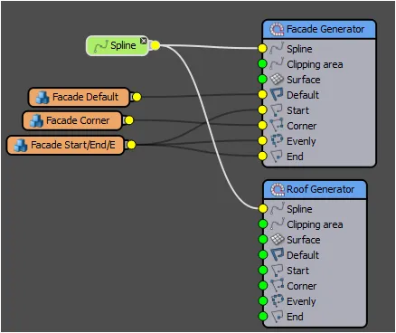
Wire the existing Spline node to the roof Generator's Spline input. By reusing the spline in this way, you can be sure that both generators follow the same path.
-
Create a new Segment Object (
)by dragging from the Items List to the Construction View. -
Go to the Properties Editor and click on the Object picker.
-
Pick the object named Roof from the scene.
-
Still in the new Segment node's Properties, change Alignment > Y to Pivot. Wire the new segment to the roof Generator's Default input.
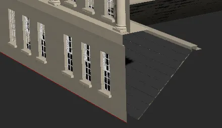
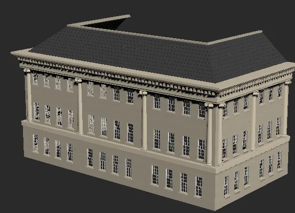
You will now have a roof in the scene, but it's at the base of the building instead of above the existing façade.
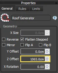
To resolve this you can use the Generator's Z Offset parameter to move the roof into the correct position. To do this:
-
Select the roof Generator.
-
Go to the Properties Panel and enter a value of 1065cm for the Z Offset parameter.
-
The roof is now in the correct position.
In the next section we'll add the balustrade, using the same Z offset value to ensure its position matches the roof.
Adding the Balustrade
-
Add a third L1S Generator (
) by dragging it from the Items List to the Construction view. -
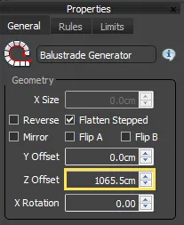
Rename the generator Balustrade Generator.
-
Go to the Properties panel and enter a value of 1065cm for the Z Offset parameter.
-
Wire the existing Spline node to the balustrade Generator's Spline input. All 3 generators are now sharing the same spline.
-
Create a new Segment Object.
-
Go to the Properties Editor and click on the Object picker.
-
Pick the object named Balustrade Start/End from the scene.
-
Still in the new Segment node's Properties, change Alignment > Y to Pivot.
-
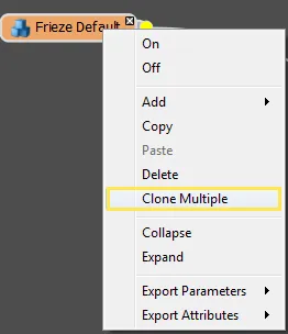
To save time we can use this node as a template to quickly add the other geometry required. To do this right-click on the new Segment and select Clone Multiple.
-
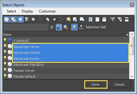
A Select Objects window opens. Pick Balustrade Default, Baluststrade Evenly, and Balustrade Corner then click Clone. RailClone will generate a new Segment node for each of the selected items.
-
Wire Balustrade Start/End to the balustrade Generator's Start input.
-
We want to reuse this segment in the End input, but it needs to be mirrored first. Instead of creating new geometry and adding an extra segment you can use a Mirror operator to flip the segment directly inside RailClone. To do this, drag a new Mirror operator (
 ) from the Items List to the Construction View. Wire Balustrade Start/End to the Mirror node's input. Wire the Mirror node's output to the Generator's End input. We will discuss operators in more detail in Chapters 10 and 11.
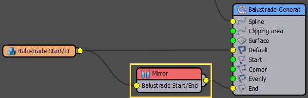
-
Wire Balustrade Default to the balustrade Generator's Default input.
-
Wire Balustrade Evenly to the balustrade Generator's Evenly input.
-
Wire Balustrade Corner to the balustrade Generator's Corner input. Like the façade example above, the corner settings now need to be adjusted.
-
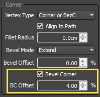
Click on the balustrade Generator and from the Properties Panel, activate Rules > Corner > Bevel Corner and set the BC Offset value to 4%.
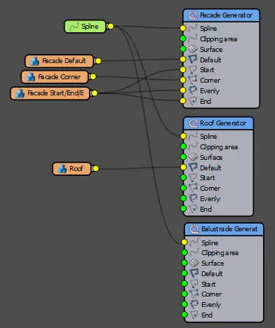
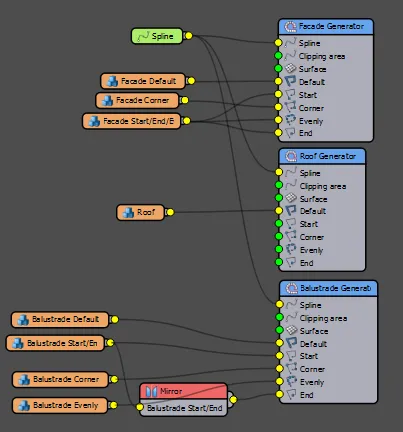
This completes the building style. The complete node tree should look like this:
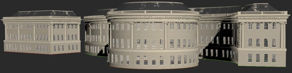
Once a style is created it's simple to reuse and re-purpose. Try cloning the object and swapping the base object by picking Spline 01 and Spline 02 RailClone deforms the geometry to follow the curves and corners of any path.
Related Tutorials
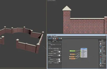
The Masonry Wall tutorial is good accompaniment to this chapter. It is intended for new users of RailClone, and provides a thorough introduction to some of the most commonly used features. By completing this exercise you will be able to use the built in library, understand the style editor, and easily create new styles.
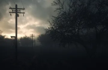
This tutorial explains in more detail the Default modes and walks you through the steps necessary to create power lines.

Stadium Tutorial Part 2,3, and 4
The stadium tutorial uses a number of L1S arrays to create advertising hoarding, seating and the crowd. These expand on the fundamentals discussed here to introduce randomisation, controlling material IDs, exporting parameters and using many useful operators.

In this tutorial we explain how to use RailClone to create your own 1D and 2D arrays to recreate a Seaside Promenade image. This tutorial builds on the foundations in this chapter and explores in detail how to use styles from the library, create new styles, use operators, edit padding and introduce 2d arrays.
For more information please see the 1D arrays - Generator L1S . Path Base Objects . Style Editor and Segments sections of the online documentation.