Techniques to deform geometry
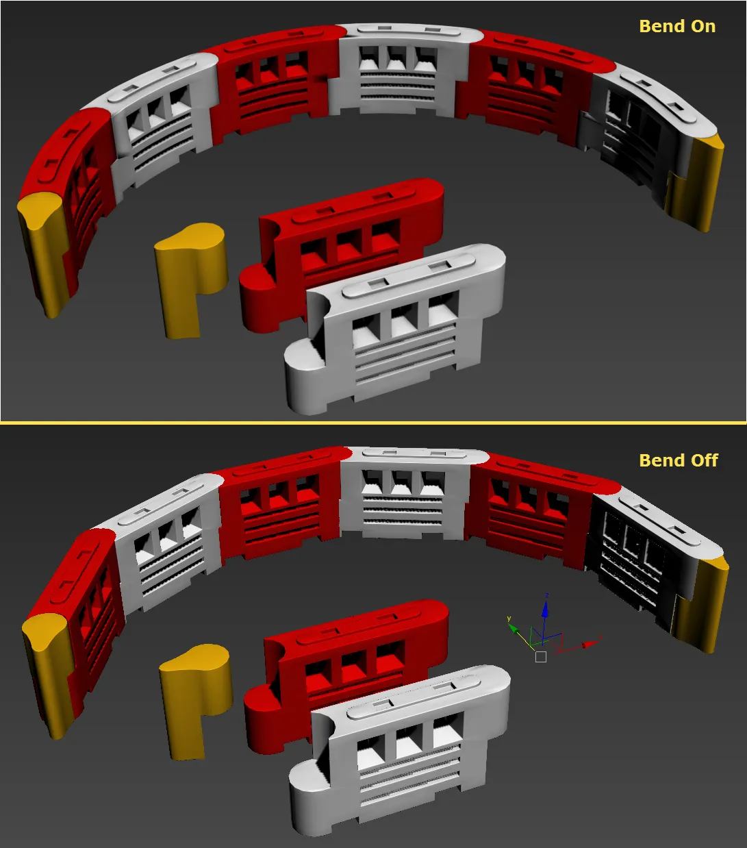
One of the most powerful features of RailClone is the ability to deform geometry to follow a path. Segments can be set to follow the curvature of a spline on the X and Y axes, with a host of additional settings to control how geometry is deformed on the Z axis. In this chapter we'll explore the many modes available, starting with turning Bend Off. deforming geometry isn't always desirable, sometimes you want to ensure it retains its original shape. Take the traffic Barrier style illustrated below for example. In the top image the segment has bend turned on, as a result each segment is smoothly deformed to follow the base spline. It looks good, but this isn't how these barriers work in real-life. Instead, we need the barrier segments to follow the spline without deforming, as in the bottom image.
Exercise: Turning off Bend
New Segments have the bend option enabled by default. In the majority of cases this is the correct behaviour, but to demonstrate how to turn Bend off, In this exercise you'll correct the barrier style used in the illustration above. Open the file called bend_slice.max and follow these steps:
-
Select rc_barrier_plastic go to the Style rollout and click
 to open the Style Editor.
 -
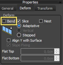
For each of the 3 Segments, go to Properties > Deform > Deform and turn off Bend.
-
The Barrier will now follow the path correctly.
Exercise: Turning off Slice
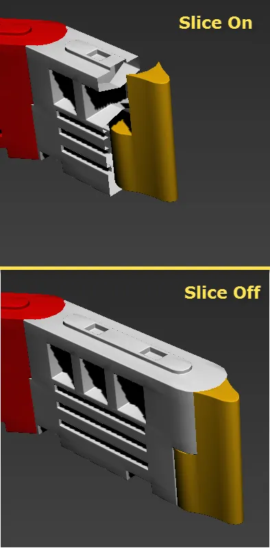
Next to Bend in the interface, there's an option to Slice the segment. When this is turned off, RailClone cuts off the part of the last segment that falls outside the path. In most cases this is the correct behaviour, but occasionally you'll want to turn this option off too. If you look at the barrier style again, you'll see that the final Segment in the array is being sliced. In this instance, turning slice off gives us a much better result, though it's important to note that this does result in the segment extending beyond the end of the spline.
To turn off Slice:
-
Make sure that rc_barrier_plastic is selected with the Style Editor is open.
-
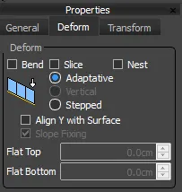
For each of the 3 Segments, go to Properties > Deform > Deform and turn off Slice.
The Barrier style is now correct.
If the deformation of segments is jagged, this is often because the interpolation value of the spline being used as a base object is too low. Instead of editing the spline, RailClone provides a feature to improve smoothing by automatically adding additional interpolation steps. To use this feature open the Style rollout and increase the Curve Steps value until you get smoother results.
Segments which have been deformed or sliced are to longer instances and contribute to the overall polygon count. To create optimal renders disable Bend and Slice for all segments that don't need it.
Deforming on the Z Axis
RailClone provides 3 additional options to control how segments deform on the Z axis: Adaptive, Vertical and Stepped. To understand these modes in more detail, try the following exercise:
Exercise: Testing X Deform modes
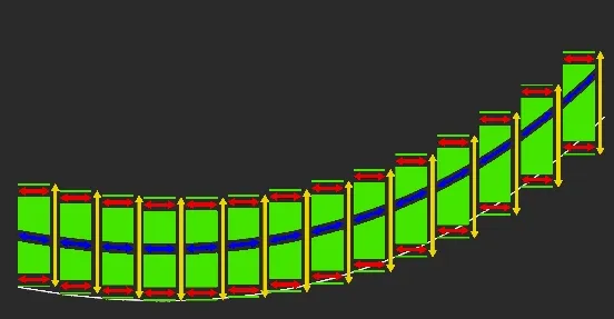
To illustrate how the modes work, open the file named z_deform_modes.max. This file contains a simplified style with a single segment. The geometry, shown below, has been designed to make it clear how the 3 different modes affect the deformation.
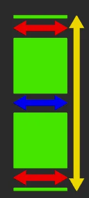
The yellow arrow helps to illustrate how the current deformation mode affects the vertical elements of the geometry, the red arrows illustrate how the current deformation mode affects the horizontal elements at the top and bottom if the geometry, and the Blue arrow illustrate how the deformation mode affects the horizontal elements in the middle if the geometry.
- To test the modes. select the RailClone object called rc_z_modes, go to the Style rollout and click to open the Style Editor.
- Select the segment and go Properties > Deform > Deform.
- Follow the steps below to activate each of the modes. After each one, scrub the timeline. The base spline is animated, so you can see how the deformation reacts to the changing shape of the path.
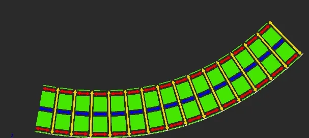
Adaptative
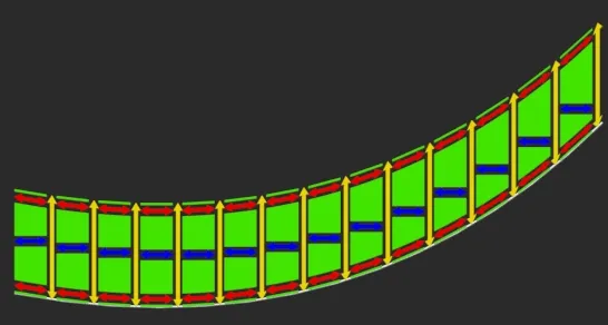
In this mode , the segment's verticals (yellow arrows) are aligned perpendicular to the path; while the horizontal elements (red and blue arrows) follow the path.
To enable Adaptive deformation mode:
- Change the Deform node to Adaptive.
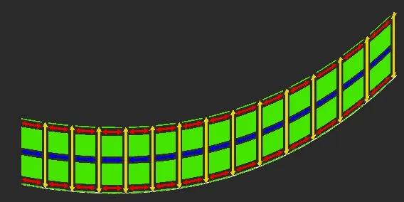
Vertical
In this mode, the vertical elements (yellow arrows) remain upright, but the horizontal elements (blue and red arrows) are deformed on the Z axis to match the elevation of the path.
To enable Vertical deformation mode:
- Change the Deform node to Vertical.
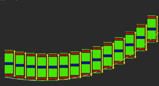
Stepped
In this mode, no deformations are applied in the Z axis, and the segment preserves its vertical alignment.
To enable Stepped deformation mode:
- Change the Deform node to Stepped.
In addition to these 3 modes, there are 2 additional hybrid nodes that combine the Vertical and Stepped deformation algorithms.
Vertical mode with Flat Top/Flat Bottom
In this mode the top and/or the bottom of a geometry is stepped (red arrows) while the areas in between follows the spline (blue arrows). The Top and Bottom values define the distance (on the Z axis) that the effect is applied, measured from the top or the bottom of the geometry.
To enable Flat Top or Flat Bottom deformation mode:
- Change the Deform node to Vertical.
- Enter a distance in for the Flat Bottom value and/or enter a distance for the Flat Top value. In the example scene, a value of 0.8m works well.
stepped mode with Vertical Top/Bottom
In this mode the top or bottom of a segment (red arrows) deform and follow the spline, leaving the middle area (blue arrows) stepped. The Top and Bottom values define the distance (on the Z axis) that the effect is applied, measured from the top or the bottom of the geometry.
To enable Vertical Top or Vertical Bottom deformation mode:
- Change the Deform node to Stepped.
- Enter a distance in for the Vertical Bottom value and/or enter a distance for the Vertical Top value.
Related Tutorials

This tutorial looks at the different ways segments can be deformed on the Z-Axis. After explaining the deformation modes we explore how to put them to good use to create a straight and spiral staircase.
For more information please see the Segments section of the online documentation.